

by William Eric McFadden
Mounting Freq-Mite Circuit Board
& Circuit Ground:
-
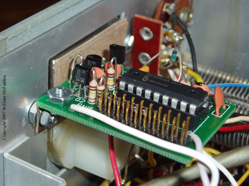
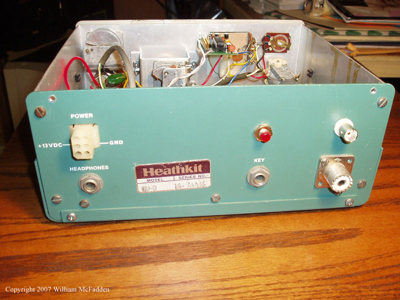
Using the supplied right-angle bracket, I mounted the Freq-Mite to the HW-8 inner front-panel at the meter mounting screw located nearest to the VFO capacitor. Because the mounting hole on the Freq-Mite circuit board is also a ground pad, circuit ground is achieved mechanically through this mount. Figure 1 shows an overall view of the mounting location. Figure 2 is a closer view of the mounting scheme.
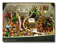
Figure 1 (click image to enlarge)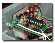
Figure 2 (click image to enlarge)
Button:
-
The button is a momentary-contact, normally-open pushbutton. To mount the button, I drilled an appropriately-sized hole in the back of the cabinet about an 1.25" above the key socket. Figure 3 shows the button mounted in this hole. From the S1 and GND pads on the Freq-Mite, I ran a twisted-pair of wires to the button. These wires are visible in Figures 1 and 2. Because there's a mechanical connection to chassis ground at the Freq-Mite mount, the GND wire is probably not necessary for operation of the device.
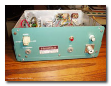
Figure 3 (click image to enlarge)
RF Pickup:
-
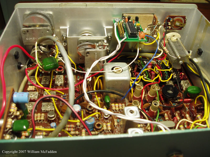
The RF signal for the Freq-Mite is picked up at the HW-8's Test Point 2 (TP2). This is located at the leg of R49 nearest to the large inductor L9 in the middle of the transciever's main circuit board. For this connection, I soldered directly to R49's leg. In Figure 4, the RF pickup is the blue wire.
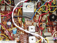
Figure 4 (click image to enlarge)

AF Out:
-
The audio-output signal from the Freq-Mite is connected to the center connection of the transceiver's AF-gain potentiometer through the supplied 100k-ohm resistor. Please note, the HW-8 uses concentric controls for on-off, AF-gain, and RF-gain. The AF-gain potentiometer is the middle of these three controls. The center connection of the potentiometer is the AF-gain output. By using this connection instead of the input, the Freq-Mite audio level remains constant--the transceiver volume can be turned all the way down for easy copy of the Freq-Mite. In figure 4, the white wire is the Freq-Mite AF Out.
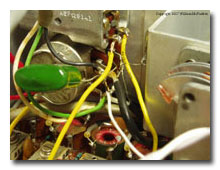
Figure 5 (click image to enlarge)
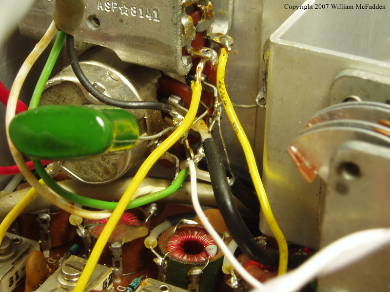
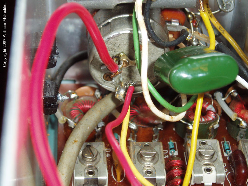
12v DC
-
DC power for the Freq-Mite is achieved with a connection to the output of the transceiver's on-off switch. This switch is the rear-most of the three concentric controls described above, and the output is the terminal with the yellow wire going to point E on the transceiver's main board. In figure 5, the DC power connection is the smaller red wire. (The larger red wire brings transceiver power from the six-pin Molex connector on the back of the rig.)
Figure 6 (click image to enlarge)
Jumpers and Operation:
-
Because of the HW-8's direct-conversion design, no offset jumpers need to be installed on the Freq-Mite. Upon application of power to the transceiver, the Freq-Mite sends "s?". Press the button once if you want readout to be at 26wpm instead of the default 13wpm. The Freq-Mite will send "i?" to ask if the frequency calculation should be inverted. Do not press the button since you don't want the calculation to be inverted. Finally, the Freq-Mite will send the prosign "AR". Any button-press at this point will cause the Freq-Mite to send the least three significant digits of the frequency. (Example: with the transceiver 40m band switch depressed and the VFO dial set to 100 for a selected frequency of 7.100 MHz, a button press will cause the Freq-Mite to send "100". If band noise prevents copy of the Freq-Mite, turn the transceiver's AF gain down all the way and press the button again.