(click image to enlarge)

by William Eric McFadden
From the manual:
-
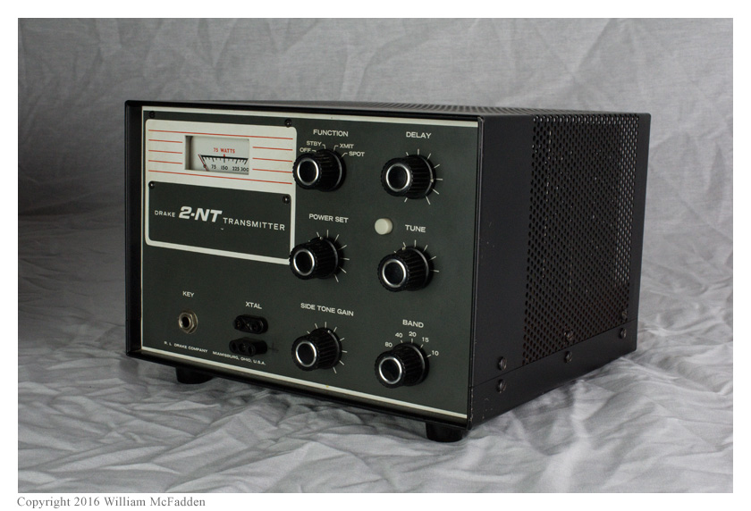
The 2-NT provides crystal controlled operation in the CW portion of the 80, 40, 20, 15 and 10 meter amateur bands.
SPECIFICATIONS: Input Power Variable to 100 watts.
(Plate current meter "red-lined" for 75 watts novice input power requirementsMode Break-in CW, Semi Break-in CW, or Manual CW with Drake 2-C or other receivers Automatic Transmit Switching Transmitter automatically "on the air" by closing hand key. Antenna Change-over Relay Provides automatic switching between transmit and receive. Mutes receiver while transmitting. Sidetone Oscillator Provides monitoring of keying with any receiver Frequency Setting Enable receiver to tune to transmitted frequency without being "on the air" Simplified Tuning Low level stages broadband. Pi-network output with fixed loading. PA plate tuning only. Low Pass Filter Prevents TVI by reducing harmonics in TV channels. Power Requirements 120 volts, 50 to 60 Hz at approximately 2.8 amperes. Dimensions 9-7/8 inches wide. 6-9/32 inches high. 9-3/23 inches deep. Weight 12-1/2 pounds Accessories Antenna Matching Network VFO Crystals TUBES AND SEMI-CONDUCTORS TUBES FUNCTION 1/2 6EA8 Crystal Oscillator 1/2 6EA8 Relay Control 12BY7 Driver Amplifier 6HF5 Power Amplifier SEMI-CONDUCTORS FUNCTION 2N3394 Sidetone Oscillator 1N483A Pulse Forming 1N483A Oscillator Switch 1N3194 Screen Rectifier 1N3194 Bias Rectifier 1N3194 High Voltage Rectifier
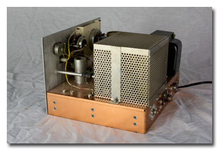
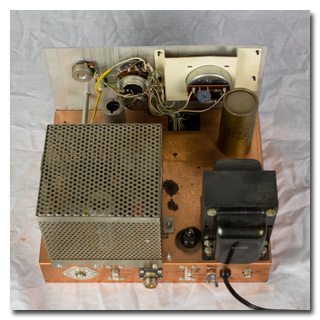
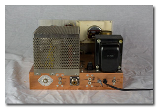
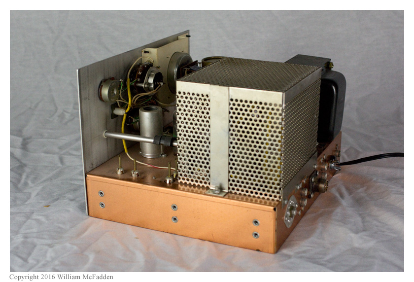
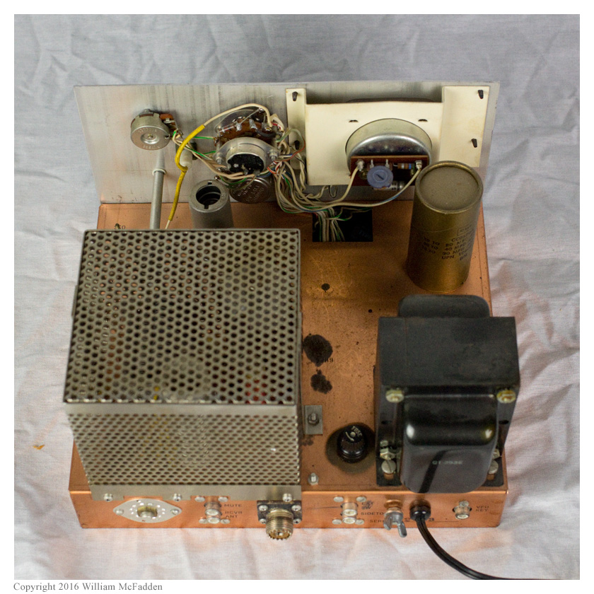
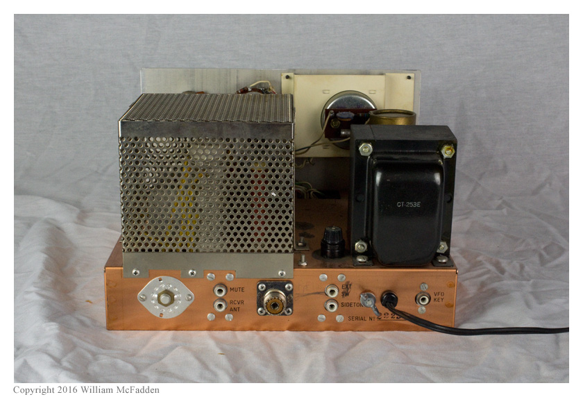
The 2-NT was introduced by the R.L. Drake Company of Miamisburg, Ohio in 1966 for Novice-class licensees. The 2-C is a vacuum tube (three) and semiconductor (twelve) hybrid design which offers CW-only output on the pre-WARC amateur bands between 3 MHz and 30 MHz (80, 40, 20, 15, and 10m).
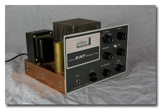
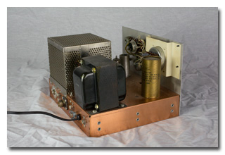
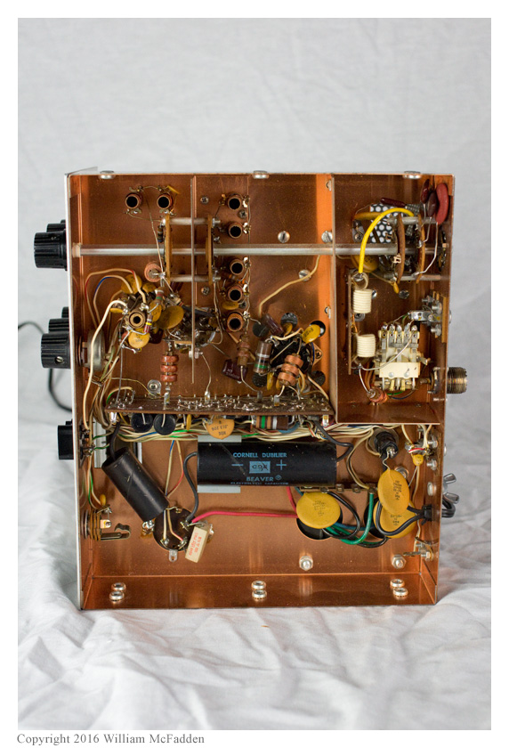
 I acquired my very clean Drake 2-NT at Hamvention 2016. Both of the CDE "Beaver" electrolytic
capacitors were leaking electrolyte so while at the Hamvention I purchased a re-cap kit from N0JMY's
Hayseed Hamfest (link).
I acquired my very clean Drake 2-NT at Hamvention 2016. Both of the CDE "Beaver" electrolytic
capacitors were leaking electrolyte so while at the Hamvention I purchased a re-cap kit from N0JMY's
Hayseed Hamfest (link).
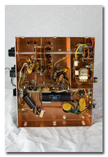
After installing the new capacitors, I enlisted the aid of friend and boat-anchor guru, Rich Post, KB8TAD (link) in performing the initial power-on tests. Rich verified I had properly installed the new electrolytic capacitors but quickly determined the oscillator wasn't running with a known-good crystal. Initial study of the schematic and examination of the rig didn't disclose an immeditate solution, so I left the transmitter with Rich for further diagnosis. Within just a couple of days, Rich had the oscillator percolating nicely after he removed what he suspects was a modification to allow use of an external VFO. Rich also fixed a bad solder joint that had been preventing the cathode current meter from operating properly.
Initial on-the-air tests with a crystal indicate the transmitter generates a nice signal and the T/R switching, receiver-mute, and sidetone-oscillator circuits all work properly. Some work still needs to be done: output on 80m isn't as high as on 40m, the Output Indicator Light isn't functioning, and the Spot signal is very weak.
In January of 2017, after using my 2-NT transmitter "rock-bound" for about seven months, I finally verified operation of the Hallicrafters HA-5 VFO I had purchased at the Hamvention 2016 for use with the 2-NT and I constructed the necessary interface cables. Initial tests indicated the HA-5 works well on 80m and 40m but it doesn't seem to generate a signal on 20m; I haven't yet tested the VFO on 15m or 10m. I'm hopeful that a dirty bandswitch is preventing operation on 20m and that cleaning the bandswitch will restore full operation of the VFO.
I've used the 2-NT/HA-5 combo on 80m and 40m and have received reports of a clean, stable signal. (And unlike the Spot function built into the 2-NT, the HA-5's Spot function provides a very nice, strong signal.)
My 2-NT's serial number, 2223, indicates my 2-NT was manufactured in late 1971 or early 1972 (source).
UPDATE 2017-02-10: After regular use, the 2-NT's T/R relay began "sticking" or "hanging". Applications of DeOxit and light burnishing of the relay contacts failed to solve the problem and I was unable to determine if the problem is mechanical or electrical. Rich Post provided guidance on the easy things to try including swapping the relay's coil polarity in case the relay has developed residual magnetism and measuring the voltage on the coil to determine if the voltage is dropping all the way to zero on key-up. Unfortunately, in measuring the coil voltage, I managed to short one side of the coil to the chassis and thereafter the transmitter failed to generate any RF output; the oscillator still ran, the T/R functioned (but still stuck), but there was no measurable output on key-down. Suspecting that the grid-block keying wasn't working, Rich suggested I measure each of the diodes in the transmitter to see if one has opened. None of the ten diodes—the manual shows only nine—tested as open. Upon hearing this, Rich generously offered to diagnose the transmitter in his shop. He was able to find two open power resistors, which he replaced; this restored proper output.
UPDATE 2017-02-14: Although output power was restored, the T/R relay sticking problem remained. Because the relay remained stuck even after power was removed from the transmitter, Rich suggested I short the relay's coil—after power was removed, of course—to determine if the problem was mechanical or electrical. I did this, and the relay did not disengage, indicating the problem was mechanical. Rich then suggested I look at somehow strengthening the relay's return spring. I was able to carefully reshape two of the relay's three arched "leaf springs"; happily, this restored the relay's proper functionality. I suspect the relay's performance will degrade again over time so I will seek a replacement relay.
UPDATE 2018-03-11: Just over a year after I was able to successfully reshape the relay's "leaf springs", the relay started sticking again. Minutes prior to the start of Novice Rig Roundup 2018 (link), I attempted again to reshape the springs but only made the situation worse, eventually breaking one of the three springs completely. I made a post on the Drake Radios forum on Yahoo! Groups (link) in the hope that someone would have a spare relay or could suggest a suitable modern replacement part. Marty, W4MY, responded and sent me a relay pulled from a 2-NT he had reluctantly decided was too far gone to restore. The new relay took about 90 minutes to install but the 2-NT's T/R switching now works smoothly and beautifully.
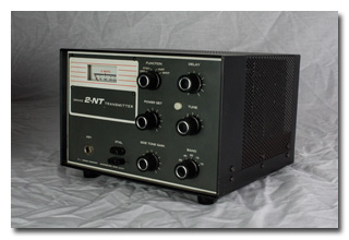
Photos
-
(click thumbnails to enlarge)
The following photographs show the original electrolytic capacitors.


Drake 2-NT Links
- Drake 2-C Receiver and 2-NT Transmitter, December, 1966 QST; members-only at ARRL
- 2-NT Manual & Schematic at BAMA
- Drake Radios at Yahoo! Groups
- VE7SL's Drake 2NT and the Novice Rig Roundup
Attributions:
- Drake 2-NT Brochure found at WB4HFN's Drake Page