Update 2015-06-05: The Radio Shack 22AWG speaker wire recommended by WD8PNL
below is no longer $6 a roll but is $16 a roll.
---
From Ron Wiesen, WD8PNL
January 02, 2004
Just ran across your "QRP Station in a Bag" and thought I would offer three
tips after reading the "The Quest for the Ideal Portable Antenna" part.
==========
Tip #1 -- consider 2-conductor speaker cable. Cable with water clear
insulation is best. Radio Shack sells a 100' roll of 22 gauge cable
(278-1385) for six bucks that is ideal. Years ago I shaved off a bunch of the
clear insulation to test it for loss. After sitting in a microwave oven for
several minutes I could not find the slightest trace of heating. If it's
lossless at microwave frequencies, the insulation is certainly lossless at HF.
What to do with a roll of speaker cable? Make a center-fed antenna. Split the
two conductors apart to form the radiator, tie a knot to prevent further
splitting under tension, and the reminder is a 2-wire transmission line that's
as lossless as Twinlead or ladder line. The conductors are continuous, so
there are no feedline/radiator joints to fail or fool with. It's rather light
weight.
My QRP operations are somewhat different than yours. Whenever I travel I take
a QRP rig, a tuner, a few heavy egg-shaped fishing sinkers, and a few tools --
nothing else. When I arrive, I go to Radio Shack for speaker cable and to a
WalMart or the like for a spool of monofilament fish line. I find two
existing supports -- generally two trees in a cemetrary. Say the supports are
50' apart, then I unroll a bit less than half that length, say 22', of speaker
cable, split the conductors and tie a knot (44' center-fed radiator). I tie an
egg-shaped fishing sinker onto the monfilament, hold the spool "open faced",
play out 3', swing it in a vertical plane like David about to slay Goliath,
take aim and let fly. I usually get it right on the first try. If not I slowly
wind it in -- the egg shape doesn't snag in tree branches. Once over or
through tree branches the sinker is heavy enough to pull the monofilament off
the spool -- sinker hits ground. Cut the line at the spool, tie it to an end
of the radiator, and cut the fishing sinker off the other end of the line.
Using the sinker again, David slays Goliath again for the other end of the
radiator. Then hoist each end of the radiator up high and tie off the fishing
line to hold it in place -- center-fed radiator is deployed and 2-wire
transmission line is in hand. Unroll the transmission line, cut off and
discard the last 4' or 5' (see Tip #3) and I'm in business.
Tip #2 -- consider either a balanced architecture tuner, or an air-core
transformer with an unbalanced tuner. Balanced tuner is best, but they aren't
manufactured today. eBay has many Johnson matchboxes, which are too large for
portable operation but just fine for home operation. A small one for QRP could
be built. For portable QRP operation I use an unbalanced T-network tuner and
an air-core RF transformer; both are homebrew. The "tip" for you is the
air-core RF transformer, rather than an "iron" core and the typical autoformer
architecture. The air-core RF transformer meets two goals: no DC continuity
in/out, no iron in the core. Mine is a bifilar winding in solenoid form. The
form is a small diameter piece of PVC pipe -- a large plastic pill bottle
might do.
The bifilar conductor is (did you guess?) speaker cable with water clear
insulation. Use 12 to 20 turns: 12 turns is fine 40m to 10m, 20 turns is fine
160m to 20m, use 15 turns for 80m to 10m. Attach the ends of one conductor to
the "Bal"anced 2-wire transmission line; attach the ends of the other
conductor to the "Un"balanced tuner. With this kind of attachment, the RF
transformer is a BalUn. Because its primary and secondary have the same number
of turns, the Z transform is 1:1 -- but you don't care about Z transform. You
care about no DC continuity in/out, and no iron. The RF transformer amounts to
link coupling. In/out coupling is magnetic (and somewhat capacitive at the
high frequencies) so the RF transformer can serve as a Un/Un, or a BalUn, or a
BalBal strictly by what attaches to its primary and secondary windings. This
is a transformer -- it is NOT an autoformer like the spark coil in your car or
like the popular BalUn windings.
Tip #3 -- consider end-to-end overall length of radiator and transmission line.
You said: I chose the 70' length based on the chart of "lengths to avoid" in
Practical Wire Antennas. I don't have that publication. I do have The A.R.R.L.
Antenna Handbook, 12th Edition, Second printing, 1970. Chapter 3 --
Transmission Lines, heading "Detuning the Line for Antenna Currents" has a
chart that shows various preferred lengths and lengths to avoid for multiband
operation. An overall length of 70' is one of the worst choices for 10m and
15m, and it's not a very good choice for 20m.
What the A.R.R.L. calls "antenna currents" is properly called "Marconi
current". By the way, they goofed in a drawing for end-feed where the
illustrated length, L, did not include any portion of the radiator -- however,
the drawing for center-feed is correct. Here are some ideal overall lengths
for 80m to 10m multiband operation not considering WARC bands: 28', 40', 58',
76', 96' (see end of Tip #1), 109', and 150' 145'. (Corrected
March 29, 2010.) Every one of these lengths is not close to being a multiple
of a half wave at EVERY band: 80m, 40m, 20m, 15m, and 10m.
An antenna has one transmission line feeding one or several radiators. The
most simple to visualize is a single radiator that is end-fed by a
transmission line. The physical length of the radiator PLUS the physical (not
electrical) length of the transmission line (coax, Twinlead, etc.) is the
overall length. This overall length determines the amount of Marconi current.
In practice there's a nebulous "length to Earth" involved but it generally is
of little consequence and merely makes the "ideal" overall lengths approximate.
Next visualize a center-fed radiator. Now try to visualize it as being two
radiators of equal length where each appears to be end-fed at opposite
terminals of the transmision line. Yes, the picture is incorrect in terms of
radiator feed. But the picture is correct in terms of overall length for
Marconi current. Those "two radiators" are of equal length, so there only is a
single overall length (more correctly there are two overall lengths that are
equal). Finally visualize those "two radiators" as unequal in length -- the
feed picture is off-center-feed, and the Marconi current picture shows two
overall lengths for consideration. Similar to one radiator with
off-center-feed, two unequal length radiators with a common center-feed (e.g.,
paralleled dipoles) has two overall lengths for consideration of Marconi
current.
==========
Tip #3 has to do with minimizing Marconi current. Tip #2 has to do with using
an RF transformer, instead of an autoformer, so there is no in/out continuity
through which Marconi current would easily pass. Tip #2 also had to do with
minimizing coupling loss by avoiding iron. Tip #1 has mostly to do with buying
low loss transmission line at $0.06 per foot that is known to withstand 500
Watt in high SWR operation.
Tip #1 has a caveat. Speaker cable doesn't shed rain water quickly. It tends
to retain rain water in its central valley. So its dielectric property alters
a lot between rain and sunshine. Thus you must touch up tuner settings often
during an uneven rain.
QRV 7.059 MHz daily 10:00 UTC to 11:45 UTC de WD8PNL -= Ron Wiesen =-
------------------------------
December 19, 2007
... the zip cord type speaker cable, with water-clear insulation, still is my
best choice for antenna material while on travel. I also use it at my home for
a permanent antenna. The cable I refer to is the cable that Radio Shack sells
on 100 foot rolls under their part number 278-1383. The speaker cable is
2-conductor, stranded 22 gauge, with water-clear insulation and sometimes the
insulation of one conductor contains a white line runner.
Years ago I tested an insulation sample and found it lossless at microwave
frequency, which assumes it also is lossless at HF. Note that the test sample
came from Radio Shack cable that did not contain a white line runner in the
insulation of one conductor. Practical experiences since that time, over years
of usage, suggest that the presence of a white line runner does not matter in
regard to loss. The dielectric property of the water-clear insulation present
in the Radio Shack speaker cable is excellent for usage at HF, and
consequently this cable performs well as a 2-wire balanced transmission line
with no noticable RF losses under severe VSWR conditions in combination with
high RF power levels. For example, the cable did not experience any voltage
flashover breakdown when it served as a 2-wire balanced transmission line at
HF with a 500 Watt PEP RF power level (CW mode) under an 80:1 VSWR condition
where at least one maximum voltage node was known to stand at some point along
its length. And conventional 2-winding air-core RF transformers constructed of
the Radio Shack speaker cable have also performed well (in BalBal, BalUn, and
UnUn applications).
In case you use the Radio Shack speaker cable as phasing lines or in other
applications where its velocity factor and/or surge impedance is important,
here is the related information as best as I've empirically determined it to
date. Velocity Factor is estimated as 0.626. Surge (i.e., characteristic)
impedance is estimated as 137 Ohm.
73 to N8VIP de WD8PNL, -= Ron =-
------------------------------
February 13, 2010 (a response to a question about air-core balun)
For an air-core RF transformer in a solenoid form, a 1.5 inch diameter form
with a single layer bifilar speaker cable winding of 15 turns is suitable for
80 Meters through 10 Meters. At the lower frequency bands the coupling is
essentially magnetic; at the upper frequency bands the RF transformer exhibits
a mix of magnetic coupling and capacitive coupling.
As to a hodge-podge winding with lots of overlap, that would reduce the
capacitive coupling somewhat (not a bad thing) but it would also reduce the
magnetic coupling (a bad thing). For a hodge-podge winding, my sense of it is
to use 20 turns in order to obtain the same inductive coupling as a single
layer winding of 15 turns.
If you want a winding configuration that will reduce the capacitive coupling,
consider a basket-weave winding. A basket-weave winding has very low
turn-to-turn capacitive coupling. Note that the vertical-peg forms that
temporarily are used to make basket-weave windings must have an ODD number of
pegs, and never an even number of pegs. Methinks 9 or 11 vertical-pegs evenly
displaced around a 4 inch diameter circle would be a suitable form for making
a basket-weave winding of speaker cable. In order to minimize the weight you
could use monofilament fishing line, rather than plastic cable ties, to retain
the weave (a tie where each peg had been located). BTW: folks who make high
performance crystal radio receivers often employ basket-weave inductors (but
wound with Litz wire), so you can Google for "crystal radio" if you're not
familiar with inductors that have a basket-weave winding.
------------------------------
February 20, 2010 (a further response to a question about air-core baluns)
Any air-core inductive reactor, beit an RF transformer used as a BalUn, an
UnUn, or a BalBal, is more power efficient than an inductive reactor that has
an iron-bearing core (e.g., a powdered-iron torroid). Because it has no iron,
an air-core inductive reactor can never "saturate" and can never exhibit iron
losses or hysteresis effects.
An air-core RF transformer with separate primary and secondary windings,
(i.e., not a single winding autoformer) is very power efficient whether, used
it's in the field or in the shack. In the field the typical RF power level is
50 Watt or less (e.g., QRP at 3 Watt), so there is no concern about failure
where the air-core RF transformer is made of the Radio Shack 22 AWG speaker
cable. Note that this particular speaker cable has been successfully used as a
low-loss balanced transmission line at a power level of 500 Watts under a VSWR
of 80:1 and with a length that assured at least one high voltage maxima was
standing somewhare along its length (and a high current maxima as well). My
sense of it is that an air-core RF transformer made of the Radio Shack speaker
cable should be good up to an RF power level of at least 300 Watts under the
worst possible terminal impedance. BTW: use of this particular Radio Shack
speaker cable (Cat# 278-1385 for the 100-foot roll) as a low-loss balanced
2-wire transmission line was the subject of the March 2009 QST article by
William A. Parmley, KR8L, titled "Zip Cord Antennas and Feed Lines For
Portable Applications" where the author used expensive laboratory test
equipment to measure its surge impedance and its velocity factor -- finding
those properties to be very close in value to empirical estimates which I
developed over years of usage.
As an alternatively for shack usagee, you could form an air-core RF
transformer from 12 AWG electrical house wire, as sold in Home Depot and other
retail hardware outlets. But you should first test the insulation of such wire
for undue loss at RF (radio frequency). To test the insulation for loss,
scrape a sample of insulation into a china dish and place the dish into a
microwave oven along with a small glass of water. Note that the water presents
the Klystron tube of the oven with a minimum RF load in order to avoid
stressing the oven by having no load at all. Run the microwave oven at full
power for a minute or two, and then remove the dish of insulation and the
glass of water. The water should be quite hot; the insulation will be
stone-cold if it has no loss at microwave frequencies. And if the insulation
has no loss at microwave frequency, you can rest assured that it has no loss
at HF. Before I acquired balanced architecture inductive link transmatches
(Johnson Matchbox) for use in my shack, I had used an air-core RF transformer
made of electrical house wire that was placed at the unbalanced antenna port
of a conventional T-match configuration transmatch.
------------------------------
March 9, 2010 (in reply to a question by N1PQ)
Peter Quinn, N1PQ:
I've been following your commentary, and have purchased a couple of
rolls of you recommended radio shack #22 speaker wire. I've wound a
fifteen turn air core transformer per your instructions around an
empty roll aids bottle.
I'm now ready to make an antenna, but would appreciate a clarification
on the antenna length(s).
You've written: "The physical length of he radiator PLUS the physical
(not electrical) length of the transmission line (coax, Twinlead,
etc.) is the over length. ... which determines the amount of Marconi
current."
And elsewhere: " ideal overall lengths ... 28', 40', 58', 76' 95' ..."
So my question: If, for example, I aimed at a 76' length, I would
include my 3' coax connection to the radio and therefore need to
subtract 3' from the 76' speaker wire transmission line.
But do I need to factor into the targeted 76' length the length of
wire used in the 15 turns of the air core transformer?
Ron Wiesen, WD8PNL:
In my text, tip #3 addresses "end-to-end overall length of radiator and
transmission line" as well as "some ideal overall lengths for 80m to 10m
multiband operation not considering WARC bands". Among others, I cited 76' as
an ideal overall length.
> So my question: If, for example, I aimed at a 76' length, I would include
> my 3' coax connection to the radio and therefore need to subtract 3' from
> the 76' speaker wire transmission line.
>
> But do I need to factor into the targeted 76' length the length of wire used
> in the 15 turns of the air core transformer?
What matters is the total overall length, which is the radiator length portion
plus the transmission line length portion up to the point where the air-core
RF transformer is located. So if the air-core RF transformer is located
between a 76' overall length and a 3' length of transmission line length
that's made of coaxial cable, then the length of the coaxial cable does not
matter because the air-core RF transformer decouples Marconi current at the
point where it is located. See illustration below.
Center-fed doublet radiator
_____________ _____________
<----------+ ||
| ||
76' overall| ||2-wire balanced
length | ||transmission line
v ||
_______||_______
| air-core |
| RF transformer |
|________________|
||
any length ||unbalanced coaxial
(e.g., 3') ||transmission line
||
As to your question, the simplistic answer is no: the length of the speaker
wire bifilar winding that forms the air-core RF transformer is not a factor.
My answer is simplistic because the physical "half-length" of the solenoid
form of the RF transformer (typically no more than a mere few inches) is a
factor, albeit a trivial factor that can be ignored.
In order to aid in your comprehension of this topic, it's helpful and valid to
liken the air-core RF transformer to a compression insulator and to liken the
overall length (i.e., radiator length portion plus transmission line length
portion) to a conductive guy line fastened to a tower. Being in close
proximity to whatever radiator is situated atop the tower, the conductive guy
line is rather tightly coupled to the near-field of the radiator. Consequently
the physical length of the conductive guy, measured from its attachment at
the top of the tower to its terminal end-point where it ties into the
compression insultator, is a length that should be selected so that is isn't
an integral multiple of a 1/2 wavelength for any frequency of operation that
is planned. Note that other segments of a guy, which are situated below the
compression insulator, are of less concern because they are more loosely
coupled to the radiator due to their greater distance from it. Just as the
compression insulator decouples a guy line, so does the air-core RF
transformer decouple a transmission line. The concern in both cases is to
elect an optimum length so that the most tightly coupled conductors
avoid/minimize their excitation by the near-field of the radiator (i.e.,
conductor length is not a resonant length). The election of that length is
what dictates the placement location of the compression insulator in one case
and the air-core RF transformer in the other case.
Below are two figures taken from the "The A.R.R.L. Antenna Handbook, 12th
Edition, Second printing, 1970. Chapter 3 -- Transmission Lines": Fig. 3-48
and Fig. 3-49.
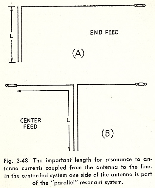 Fig. 3-48
In the case of an end-fed radiator, Fig. 3-48(A) is misleading because it
assumes only those cases where the radiator is of a resonant length (e.g.,
1/2 wavelength). For cases where the radiator is not a resonant length,
Fig. 3-48(A) is incorrect. In all cases it is correct to consider the overall
length, where overall length includes the length of the transmission line
portion, which is denoted as length L in Fig. 3-48(A), plus the entire length
of the end-fed radiator portion.
Fig. 3-48
In the case of an end-fed radiator, Fig. 3-48(A) is misleading because it
assumes only those cases where the radiator is of a resonant length (e.g.,
1/2 wavelength). For cases where the radiator is not a resonant length,
Fig. 3-48(A) is incorrect. In all cases it is correct to consider the overall
length, where overall length includes the length of the transmission line
portion, which is denoted as length L in Fig. 3-48(A), plus the entire length
of the end-fed radiator portion.
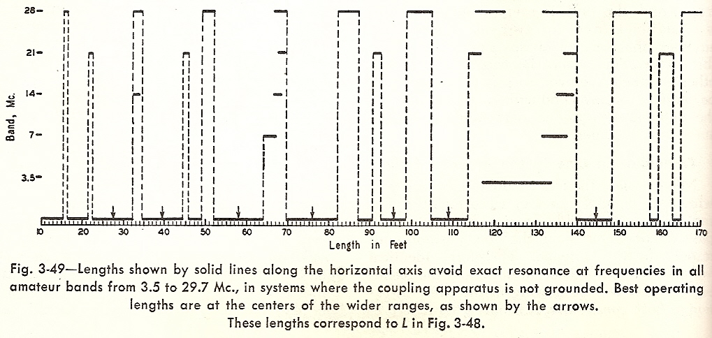 Fig. 3-49
 illustrates lengths only for the conventional Amateur Radio bands of
80M, 40M, 20M, 15M, and 10M because it was published prior to subsequent
introduction of the Amateur Radio bands 60M, 30M, 17M, and 12M. You can use
the formula below in order to determine the lengths to avoid for bands 60M,
30M, 17M, and 12M.
Length (feet) of 1/2 wavelength multiples to avoid = 467.4 / frequency (MHz)
For example, the end-frequencies of the 30M band are: 10.15 MHz and 10.1 MHz.
Per the formula above, the corresponding 1/2 wavelengths are: 46.0' and 46.3'.
Consequently all overall lengths (i.e., transmission line portion plus
radiator portion) ranging from 46.0' through 46.3' should be avoided for
operation on the 30M band. Furthermore, every integral multiple of this range
of lengths (e.g., 2nd multiple range is 92.1' through 92.6') should be avoided.
Given that the 30M band and the 15M band have an approximate factor of 2
relationship between them, every even multiple length that should be avoided
for 15M band operation should likewise be avoided for 30M band operation.
Note that your election of 76' for overall length is somewhat problematic if
operation in the 17M band is anticipated. The end-frequencies of the 17M band
are: 18.168 MHz and 18.068 MHz. Per the formula above, the corresponding 1/2
wavelengths are: 25.7' and 25.9'. The third integral multiple of this range of
lengths (77.2' through 77.6') is rather close to 76'.
If practical, a grid-dip meter can be used in order to check the antenna
system for avoidance of resonance at, and near, all of the frequencies that
are anticipated for usage. See illustration below. The air-core RF transformer
is temporarily removed and, in its place, the two conductors of the
transmission line are shorted together and loosely coupled to a grid-dip meter
by a small value capacitor.
Center-fed doublet radiator
_____________ _____________
<----------+ ||
| ||
76' overall| ||2-wire balanced
length | ||transmission line
v ||
++temporarily shorted terminals
|
===== temporarily attached coupling capacitor
| (small value e.g., 10 pF or less)
____|_____
| Grid-dip |
| Meter |
|__________|
I hope I've sufficiently clarified everything. If not, then please send me
another email message and let me know of anything that remains unclear to
you. -- WD8PNL
------------------------------
March 25, 2010
> Hi Ron,
>
> Here's where I'm at with my Rolaids and speaker wire.
>
> 1. Using a 76' length up ... with a 22' split at the apex and a 54' feed to
> the rolaids winding. The apex is up about 30'; the ends similarly.
>
> 2. No joy in trying to load 80m with the KX-1; but fine on 40m and 20m.
>
> In thinking about these results I wonder if:
>
> a. I should extend the overall length to one of your recommended 96' or
> 109' or 150' feet so as to load 80m
>
> b. I need to snip the three heat shrink tubes and better separate all
> the wires to and from the bifilar winding. it's dawning on me that I
> may have incorrectly placed the wires so close together at the in
> feed, and the out feed that the balun can't do it's job. maybe the
> photo will show the proximity.
>
> when your time permits, please make any corrective suggestions.
>
> 73,
> peter, n1pq
Hello Peter:
Thanks for sending me a picture of your RF transformer that has a Rolaids
bottle as its solenoid form. It's small and light weight so it'll be ideal for
portable operations afield. Perhaps the Rolaids bottle can do double-duty and
also serve as a carrying container for small parts taken afield.
Apparently the internal antenna tuner unit of the Elecraft KX-1 (the ATU is
the narrow circuit board inside the case) can't handle the terminal impedance
that the feedline presents on 80 Meters to the antenna port. Likely the
resistive component of the terminal impedance is too small in magnitude,
despite whichever sign the reactive component happens to be: negative if
capacitive flavor, or positive if inductive flavor. But I'm glad that the
terminal impedance which the feedline manifests on 40 Meters and on 20 Meters
is within the range that the internal antenna tuner unit can manage.
With respect to obtaining a suitable terminal impedance on 80 Meter operation
that is within the impedance matching ability of the KX-1's internal antenna
tuner unit, there are several remedial possibilities.
One remedy addresses 80 Meter operation without disturbing the present and
acceptable situation for 40 Meters and 20 Meters that the feedline manifests.
That remedy is to employ a 2-stage impedance match on 80 Meters, where an
external transmission line coupler provides a partial 1st-stage impedance
transformation while the internal antenna tuner unit of the KX-1 provides the
2nd-stage impedance transformation. Albeit used for operation on 80 Meters in
order to achieve a 2-stage impedance match, note that the external
transmission line coupler is removed for operation on 40 Meters and on 20
Meters, where only the existing single-stage impedance transformation provided
by the internal antenna tuner unit of the KX-1 is required.
In fixed station operation, use of an external transmission line coupler is
practical. But in portable station operations, an external transmission line
coupler amounts to extra volume and extra weight to be carried afield, which
may prove impractical. In low power portable operation it is quite practical
to use an impedance tranforming network of fixed-value components that
tolerate only modest current and voltage levels. Rather than an external
transmission line coupler which houses high-power variable-value components,
in low power portable operation the requisite partial 1st-stage impedance
transformation can be provided by using low-power fixed-value components. The
low-power fixed-value components, connected in a suitable circuit topography
to deliver a wide-bandwidth 1st-stage fixed-transform of impedance, can reside
within a detachable add-on fixture which is so ultra-light in weight
and small in size that it may be mounted directly onto the antenna jack of the
KX-1.
Sundry other remedies to address 80 Meter operation will, for better or for
worse, influence the situation for operation on 40 Meters and on 20 Meters. It
s possible that the influence might be beneficial in nature for operation on
40 Meters or 20 Meters, or for both. On the other hand, it's also possible
that such influence might be detrimental in nature to such a degree that the
influence precludes operation on 40 Meters or/and operation on 20 Meters. In
all such remedies it is an intentional change in the selected length of the
transmission line (i.e., 2-wire balanced, speaker cable) that produces a
different terminal impedance that the feedline presents on all of the bands of
interest: 80 Meters, 40 Meters, and 20 Meters.
One approach is to seek a particular length of transmission line that is
selected in order that two desirable attributes emerge simultaneously:
#1 -- the length of transmission line produces acceptable terminal impedances,
and #2 -- when considered in series with the radiator length, the "total
overall length" of the antenna is one that minimizes Marconi current.
> extend the overall length to one of your recommended 96' or 109' or 150'
> feet so as to load 80m
Your statement above bears in mind desirable attribute #2. Overall lengths of
96' and 109' minimize Marconi current. But an overall length of 150' doesn't
suppress Marconi current under 10 Meter operation. I can now see that this was
an error that I made in my correspondence to Eric McFadden (WD8RIF) on January
2, 2004 in the second paragraph of "Tip #3" where, instead of 150', I should
have stated an overall length of 145'. I apologize for this error. I've
contacted Eric in order for him to correct my error at his website. (This
correction has been made -- WD8RIF)
Predictive mathematic calculation related to desirable attribute #1 can be
done. But seeking the solution to the associated "simultaneous equations" is
not an easily accomplished task. If you wish to tackle predictive mathematic
calculation, you will need the following data:
o velocity factor of the transmission line,
o surge impedance (a.k.a. characteristic impedance) of the transmission line,
o and the intrinsic impedance of space.
Used as a 2-wire balanced transmission line, the 2-conductor Radio Shack
speaker cable has:
o a velocity factor of 0.7,
o and a surge impedance of 145.6 ohm.
According to Mr. Einstein and other paragons of theoretic physics, when it is
expressed in its mathematic form the intrinsic impedance of space is equal to
(ç¶ ¼ e¶)^§ where: the ratio (¼) of the magnetic permeability of a vacuum (ç¶)
versus the permittivity of a vacuum (e¶) is reduced to its 2nd root power (^§)
i.e., its square root. As it pertains to electromagnetic radiation, the folks
who study the electronics realm of physics define the intrinsic impedance of
space as the free-space ratio of the complex amplitude of the electric field
(E) versus the complex amplitude of the magnetic field (I). And when that is
expressed in a simple R=E/I form and then computed, the intrinsic impedance of
space amounts to the theoretical value of 376.7 "ohm". This theoretical value
is the basis that is used to determine the impedance of all radiators of
electromagnetic radiation. Because every radiator is "coupled" to space via
the law of electrostatics and via the law of magnetics, the specific
3-dimensional "shape" of any radiator is solely what "transforms" the 376.7
"ohm" intrinsic impedance of space into the specific impedance that the
radiator exhibits at every point of its 3-dimensional shape.
Your center-fed, 44' long, doublet radiator "transforms" the 376.7 "ohm"
intrinsic impedance of space into a complex impedance that is different on
each Amateur Radio band. Manifested at the feed point of the radiator, each
one of the various complex impedances represents a particular "load" for the
energy that is fed to the radiator by the transmission line. My estimate of
these feed point "load" impedances at 80 Meters and 40 Meters and 20 Meters
are tabulated below. The impedances are expressed in Cartesian coordinates as
series resistive (R) and series reactive (ÝjX) components, and I've converted
them to their corresponding polar coordinates (Z and phase angle) which are
suitable for plotting on a Smith chart.
+---------------------------------------------------------------------+
| Feed Point Complex Impedance of Center-fed 44' Doublet Radiator |
+--------------------+----------------------+-------------------------+
| Band and Frequency | R and ÝjX components | Polar Z and phase angle |
+--------------------+----------------------+-------------------------+
| 80 Meters 03.5 MHz | R=5 ÝjX=-3000 | Z=3000.0042 89.90¯ |
| 40 Meters 07.0 MHz | R=20 ÝjX=-1150 | Z=1150.1739 -89.00¯ |
| 20 Meters 14.0 MHz | R=150 ÝjX=+600 | Z=618.4658438 75.96¯ |
+--------------------+----------------------+-------------------------+
> No joy in trying to load 80m with the KX-1; but fine on 40m and 20m.
Using the feed point complex impedances listed above as the "load", the
complex impedances that are present at the "source" end of a feedline can be
calculated by applying the velocity factor and surge impedance of whatever
type of transmission line serves as the feedline. Note that in every case
under consideration here, 2-conductor Radio Shack speaker cable serves as the
feedline. The complex impedances which manifest at the "source" end terminals
of the Radio Shack speaker cable depend upon the cable length, and vary with
frequency. See the table below where details of 9 cases (#1 through #9) are
listed.
Case #1 is your present arrangement. The feedline length is 54'. This is the
overall 76' length of Radio Shack speaker cable, which is effective for
suppressing Marconi current, minus the 22' portion which is used to form the
44' long center-fed radiator. Note #1 identifies the reason why you find 80
Meter operation to be problematic. At 3.5 MHz the feedpoint complex impedance
of R=5 ÝjX=-3000, as transformed by a 0.275 wavelength (WL) feedline,
manifests a complex impedance of R=0.49 ÝjX=+29.74 at the feedline terminals.
The R component is very low and likely can not be tolerated by the internal
antenna tuner of the KX-1.
As is true of Case #1, when you include the 22' half of the 44' center-fed
doublet radiator, the overall lengths in Case #2 (96'), Case #3 (109'), and
Case #4 (145') are effective lengths for suppressing Marconi current. Unlike
Case #1, under 80 Meter operation Case #2, Case #3, and Case #4 are less
problematic in regard to the impedance matching range of the internal antenna
tuner of the KX-1. The least problematic under 80 Meter operation is Case #3,
which manifests a complex impedance of R=7.77 ÝjX=+445.7 at the feedline
terminals.
+-----------------+------+-----------+-------------------------------------+
| Feedline Length | Band | Frequency | Feedline Terminal Complex Impedance |
| in Feet | in WL | | | R ÝjX | Z angle |
+-----------------+------+-----------+-------------------------------------+
| 54.000 | 0.275 | 80 M | 3.5 MHz | 0.49 +29.74 | 29.74 +89.06¯ |#1
| " | 0.549 | 40 M | 7.0 MHz | 4.84 -313.3 | 313.33 -89.11¯ |
| " | 1.098 | 20 M | 14.0 MHz | 57.74 -342.79 | 347.62 -80.44¯ |
+-----------------+------+-----------+-------------------------------------+
| 74.000 | 0.376 | 80 M | 3.5 MHz | 1.55 +162.12 | 162.13 +89.45¯ |#2
| " | 0.752 | 40 M | 7.0 MHz | 1.16 +20.46 | 20.5 +86.74¯ |
| " | 1.505 | 20 M | 14.0 MHz | 217.88 +667.31 | 701.97 +71.92¯ |
+-----------------+------+-----------+-------------------------------------+
| 87.000 | 0.442 | 80 M | 3.5 MHz | 7.77 +445.7 | 445.77 +89.0¯ |#3
| " | 0.885 | 40 M | 7.0 MHz | 4.22 +211.84 | 211.88 +88.86¯ |
| " | 1.769 | 20 M | 14.0 MHz | 9.2 -15.16 | 17.74 -58.76¯ |
+-----------------+------+-----------+-------------------------------------+
| 123.000 | 0.625 | 80 M | 3.5 MHz | 1.5 -131.17 | 131.18 -89.35¯ |#4
| " | 1.251 | 40 M | 7.0 MHz | 1.7 +18.78 | 18.85 +84.82¯ |
| " | 2.501 | 20 M | 14.0 MHz | 190.64 +598.65 | 628.27 +72.34¯ |
+-----------------+------+-----------+-------------------------------------+
| 78.686 | 0.400 | 80 M | 3.5 MHz | 2.38 +221.29 | 221.31 +89.38¯ |#5
| " | 0.800 | 40 M | 7.0 MHz | 1.5 +68.18 | 68.2 +88.74¯ |
| " | 1.600 | 20 M | 14.0 MHz | 56.73 -330.94 | 335.77 -80.27¯ |
+-----------------+------+-----------+-------------------------------------+
| 89.505 | 0.455 | 80 M | 3.5 MHz | 13.78 +606.83 | 606.98 +88.70¯ |#6
| " | 0.910 | 40 M | 7.0 MHz | 42.51 +911.98 | 912.97 +87.33¯ |
| " | 1.820 | 20 M | 14.0 MHz | 9.62 +31.6 | 33.03 +73.06¯ |
+-----------------+------+-----------+-------------------------------------+
| 98.357 | 0.500 | 80 M | 3.5 MHz | 316.5 -2966.01 | 2982.84 -83.91¯ |#7
| " | 1.000 | 40 M | 7.0 MHz | 86.76 -1143.85 | 1147.14 -85.66¯ |
| " | 2.000 | 20 M | 14.0 MHz | 174.49 +586.37 | 611.79 +73.43¯ |
+-----------------+------+-----------+-------------------------------------+
| 118.029 | 0.600 | 80 M | 3.5 MHz | 2.02 -180.54 | 180.55 -89.36¯ |#8
| " | 1.200 | 40 M | 7.0 MHz | 1.63 -27.70 | 27.74 -86.63¯ |
| " | 2.400 | 20 M | 14.0 MHz | 16.93 +125.73 | 126.86 +82.33¯ |
+-----------------+------+-----------+-------------------------------------+
| 137.700 | 0.700 | 80 M | 3.5 MHz | 1.07 -39.48 | 49.5 -88.44¯ |#9
| " | 1.400 | 40 M | 7.0 MHz | 8.06 +263.4 | 263.52 +88.25¯ |
| " | 2.800 | 20 M | 14.0 MHz | 9.97 +12.99 | 16.37 +52.50¯ |
+-----------------+------+-----------+-------------------------------------+
| Notes: |
| |
| Note #1: Including the 22' half of the 44' center-fed doublet radiator, |
| the overall length is 76', which is an effective length for suppressing |
| Marconi current. This is the present arrangement. At 3.5 MHz, the |
| feedline manifests a complex impedance with its R component of 0.49 ohm. |
| This is so low that it presumably is beyond the impedance matching range |
| of the internal antenna tuner of the KX-1. |
| |
| Note #2: Including the 22' half of the 44' center-fed doublet radiator, |
| the overall length is 96', which is an effective length for suppressing |
| Marconi current. |
| |
| Note #3: Including the 22' half of the 44' center-fed doublet radiator, |
| the overall length is 109', which is an effective length for suppressing |
| Marconi current. |
| |
| Note #4: Including the 22' half of the 44' center-fed doublet radiator, |
| the overall length is 145', which is an effective length for suppressing |
| Marconi current. |
| |
| Note #5: Including the 22' half of the 44' center-fed doublet radiator, |
| the overall length is 100.686', which is an effective length for |
| suppressing Marconi current with the exception of operation at 28.0 MHz. |
| |
| |
| For 3.5 MHz operation only, consider providing the KX-1 with a 1st-stage |
| impedance transformation via a network of suitable topography. |
| |
| At 3.5 MHz, the 78.686' length of feedline manifests a complex impedance |
| with a very low R component of 2.38 ohm. In this situation, a Low-pass |
| L-network is a suitable topography for a 1st-stage fixed-transform of |
| impedance. Its shunt capacitor connects across the antenna jack of the |
| KX-1; its inductor connects in series with the feedline. See |
| illustration below. |
| |
| O---+----------------O velocity factor=0.7 |
| / | C = 255.2pF \ |
| R=50.0 ÝjX=0 KX-1 ===== Feedline R=2.38 ÝjX=+221.29 |
| \ | L = 41.47uH / |
| O---+-----mmmmmmm----O surge impedance=145.6 |
| |
| Note #6: Including the 22' half of the 44' center-fed doublet radiator, |
| the overall length is 111.505', which is an effective length for |
| suppressing Marconi current. |
| |
| For 3.5 MHz operation only, consider providing the KX-1 with a 1st-stage |
| impedance transformation via a network of suitable topography. |
| |
| At 3.5 MHz, the 89.505' length of feedline manifests a complex impedance |
| with a very low R component of 13.78 ohm. In this situation, a Low-pass |
| L-network is a suitable topography for a 1st-stage fixed-transform of |
| impedance. Its shunt capacitor connects across the antenna jack of the |
| KX-1; its inductor connects in series with the feedline. See |
| illustration below. |
| |
| O---+----------------O velocity factor=0.7 |
| / | C = 117.9pF \ |
| R=50.0 ÝjX=0 KX-1 ===== Feedline R=13.78 ÝjX=+606.83 |
| \ | L = 48.05uH / |
| O---+-----mmmmmmm----O surge impedance=145.6 |
| |
| Note #7: Including the 22' half of the 44' center-fed doublet radiator, |
| the overall length is 120.357', which is an unfavorable length because |
| it abets the flow of Marconi current for operation at 3.5 MHz and at 28 |
| MHz. An RF transformer can be placed at a point along the transmision |
| line in order to divide it into two segments with lengths that suppress |
| Marconi current. |
| |
| For 3.5 MHz operation only, consider providing the KX-1 with a 1st-stage |
| impedance transformation via a network of suitable topography. |
| |
| At 3.5 MHz, the 98.357' length of feedline manifests a complex impedance |
| with a very high ÝjX= component of -2966.01 ohm. In this situation, any |
| of three networks have suitable topography for a 1st-stage |
| fixed-transform of impedance: a Low-pass L-network, a High-pass |
| L-network, or a High-pass T-network. |
| |
| The Low-pass L-network is illustrated below. Its shunt capacitor |
| connects across the antenna jack of the KX-1; its inductor connects in |
| series with the feedline. |
| |
| O---+----------------O velocity factor=0.7 |
| / | C = 25.8pF \ |
| R=50.0 ÝjX=0 KX-1 ===== Feedline R=316.50 ÝjX=-2966.01 |
| \ | L = 50.4uH / |
| O---+-----mmmmmmm----O surge impedance=145.6 |
| |
| The High-pass L-network is illustrated below. Its shunt inductor |
| connects across the feedline; its capacitor connects in series with the |
| feedline. Among the three networks, the High-pass L-network delivers |
| the greatest bandwidth. |
| |
| O----------------+---O velocity factor=0.7 |
| / L = 36.16uH } \ |
| R=50.0 ÝjX=0 KX-1 } Feedline R=316.50 ÝjX=-2966.01 |
| \ C = 42.1pF || } / |
| O-----------||---+---O surge impedance=145.6 |
| || |
| |
| The High-pass T-network is illustrated below. Its shunt inductor |
| connects to the junction between its two capacitors; its lesser value |
| capacitor connects in series to the antenna jack of the KX-1; its |
| greater value capacitor connects in series with the feedline. |
| |
| O------------+-------O velocity factor=0.7 |
| / L = 37.54uH } \ |
| R=50.0 ÝjX=0 KX-1 } Feedline R=316.50 ÝjX=-2966.01 |
| \ || } || / |
| O--||--------+----||-O surge impedance=145.6 |
| C = 35.0pF || C = 100.0pF || |
| |
| Note #8: Including the 22' half of the 44' center-fed doublet radiator, |
| the overall length is 140.029', which is an effective length for |
| suppressing Marconi current for operation at 3.5 MHz and at 7.0 MHz. It |
| is a marginally effective length for operation at 14.0 MHz, but it is an |
| ineffective length for operation at 21.0 MHz and 28.0 MHz. |
| |
| For 3.5 MHz operation only, consider providing the KX-1 with a 1st-stage |
| impedance transformation via a network of suitable topography. |
| |
| At 3.5 MHz, the 118.029' length of feedline manifests a complex |
| impedance with a ÝjX component that is negative (i.e., capacitive) and a |
| very low R component of 2.02 ohm. In this situation, a High-pass |
| L-network is a suitable topography for a 1st-stage fixed-transform of |
| impedance. Its shunt inductor connects across the feedline; its |
| capacitor connects in series with the feedline. See illustration below. |
| |
| O----------------+---O velocity factor=0.7 |
| / L = 6.56uH } \ |
| R=50.0 ÝjX=0 KX-1 } Feedline R=2.02 ÝjX=-180.54 |
| \ C = 63.8pF || } / |
| O------------||--+---O surge impedance=145.6 |
| || |
| |
| Note #9: Including the 22' half of the 44' center-fed doublet radiator, |
| the overall length is 159.700', which is an effective length for |
| suppressing Marconi current with the exception of operation at 21.0 MHz. |
| |
| For 3.5 MHz operation only, consider providing the KX-1 with a 1st-stage |
| impedance transformation via a network of suitable topography. |
| |
| At 3.5 MHz, the 137.7' length of feedline manifests a complex impedance |
| with a ÝjX component that is negative (i.e., capacitive) and a very low |
| R component of 1.07 ohm. In this situation, a High-pass L-network is a |
| suitable topography for a 1st-stage fixed-transform of impedance. Its |
| shunt inductor connects across the feedline; its capacitor connects in |
| series with the feedline. See illustration below. |
| |
| O----------------+---O velocity factor=0.7 |
| / L = 1.55uH } \ |
| R=50.0 ÝjX=0 KX-1 } Feedline R=1.07 ÝjX=-39.48 |
| \ C = 190.4pF || } / |
| O------------||--+---O surge impedance=145.6 |
| || |
| |
+--------------------------------------------------------------------------+
73 to N1PQ de WD8PNL, -= Ron Wiesen =-
Fig. 3-49
Fig. 3-49 illustrates lengths only for the conventional Amateur Radio bands of
80M, 40M, 20M, 15M, and 10M because it was published prior to subsequent
introduction of the Amateur Radio bands 60M, 30M, 17M, and 12M. You can use
the formula below in order to determine the lengths to avoid for bands 60M,
30M, 17M, and 12M.
Length (feet) of 1/2 wavelength multiples to avoid = 467.4 / frequency (MHz)
For example, the end-frequencies of the 30M band are: 10.15 MHz and 10.1 MHz.
Per the formula above, the corresponding 1/2 wavelengths are: 46.0' and 46.3'.
Consequently all overall lengths (i.e., transmission line portion plus
radiator portion) ranging from 46.0' through 46.3' should be avoided for
operation on the 30M band. Furthermore, every integral multiple of this range
of lengths (e.g., 2nd multiple range is 92.1' through 92.6') should be avoided.
Given that the 30M band and the 15M band have an approximate factor of 2
relationship between them, every even multiple length that should be avoided
for 15M band operation should likewise be avoided for 30M band operation.
Note that your election of 76' for overall length is somewhat problematic if
operation in the 17M band is anticipated. The end-frequencies of the 17M band
are: 18.168 MHz and 18.068 MHz. Per the formula above, the corresponding 1/2
wavelengths are: 25.7' and 25.9'. The third integral multiple of this range of
lengths (77.2' through 77.6') is rather close to 76'.
If practical, a grid-dip meter can be used in order to check the antenna
system for avoidance of resonance at, and near, all of the frequencies that
are anticipated for usage. See illustration below. The air-core RF transformer
is temporarily removed and, in its place, the two conductors of the
transmission line are shorted together and loosely coupled to a grid-dip meter
by a small value capacitor.
Center-fed doublet radiator
_____________ _____________
<----------+ ||
| ||
76' overall| ||2-wire balanced
length | ||transmission line
v ||
++temporarily shorted terminals
|
===== temporarily attached coupling capacitor
| (small value e.g., 10 pF or less)
____|_____
| Grid-dip |
| Meter |
|__________|
I hope I've sufficiently clarified everything. If not, then please send me
another email message and let me know of anything that remains unclear to
you. -- WD8PNL
------------------------------
March 25, 2010
> Hi Ron,
>
> Here's where I'm at with my Rolaids and speaker wire.
>
> 1. Using a 76' length up ... with a 22' split at the apex and a 54' feed to
> the rolaids winding. The apex is up about 30'; the ends similarly.
>
> 2. No joy in trying to load 80m with the KX-1; but fine on 40m and 20m.
>
> In thinking about these results I wonder if:
>
> a. I should extend the overall length to one of your recommended 96' or
> 109' or 150' feet so as to load 80m
>
> b. I need to snip the three heat shrink tubes and better separate all
> the wires to and from the bifilar winding. it's dawning on me that I
> may have incorrectly placed the wires so close together at the in
> feed, and the out feed that the balun can't do it's job. maybe the
> photo will show the proximity.
>
> when your time permits, please make any corrective suggestions.
>
> 73,
> peter, n1pq
Hello Peter:
Thanks for sending me a picture of your RF transformer that has a Rolaids
bottle as its solenoid form. It's small and light weight so it'll be ideal for
portable operations afield. Perhaps the Rolaids bottle can do double-duty and
also serve as a carrying container for small parts taken afield.
Apparently the internal antenna tuner unit of the Elecraft KX-1 (the ATU is
the narrow circuit board inside the case) can't handle the terminal impedance
that the feedline presents on 80 Meters to the antenna port. Likely the
resistive component of the terminal impedance is too small in magnitude,
despite whichever sign the reactive component happens to be: negative if
capacitive flavor, or positive if inductive flavor. But I'm glad that the
terminal impedance which the feedline manifests on 40 Meters and on 20 Meters
is within the range that the internal antenna tuner unit can manage.
With respect to obtaining a suitable terminal impedance on 80 Meter operation
that is within the impedance matching ability of the KX-1's internal antenna
tuner unit, there are several remedial possibilities.
One remedy addresses 80 Meter operation without disturbing the present and
acceptable situation for 40 Meters and 20 Meters that the feedline manifests.
That remedy is to employ a 2-stage impedance match on 80 Meters, where an
external transmission line coupler provides a partial 1st-stage impedance
transformation while the internal antenna tuner unit of the KX-1 provides the
2nd-stage impedance transformation. Albeit used for operation on 80 Meters in
order to achieve a 2-stage impedance match, note that the external
transmission line coupler is removed for operation on 40 Meters and on 20
Meters, where only the existing single-stage impedance transformation provided
by the internal antenna tuner unit of the KX-1 is required.
In fixed station operation, use of an external transmission line coupler is
practical. But in portable station operations, an external transmission line
coupler amounts to extra volume and extra weight to be carried afield, which
may prove impractical. In low power portable operation it is quite practical
to use an impedance tranforming network of fixed-value components that
tolerate only modest current and voltage levels. Rather than an external
transmission line coupler which houses high-power variable-value components,
in low power portable operation the requisite partial 1st-stage impedance
transformation can be provided by using low-power fixed-value components. The
low-power fixed-value components, connected in a suitable circuit topography
to deliver a wide-bandwidth 1st-stage fixed-transform of impedance, can reside
within a detachable add-on fixture which is so ultra-light in weight
and small in size that it may be mounted directly onto the antenna jack of the
KX-1.
Sundry other remedies to address 80 Meter operation will, for better or for
worse, influence the situation for operation on 40 Meters and on 20 Meters. It
s possible that the influence might be beneficial in nature for operation on
40 Meters or 20 Meters, or for both. On the other hand, it's also possible
that such influence might be detrimental in nature to such a degree that the
influence precludes operation on 40 Meters or/and operation on 20 Meters. In
all such remedies it is an intentional change in the selected length of the
transmission line (i.e., 2-wire balanced, speaker cable) that produces a
different terminal impedance that the feedline presents on all of the bands of
interest: 80 Meters, 40 Meters, and 20 Meters.
One approach is to seek a particular length of transmission line that is
selected in order that two desirable attributes emerge simultaneously:
#1 -- the length of transmission line produces acceptable terminal impedances,
and #2 -- when considered in series with the radiator length, the "total
overall length" of the antenna is one that minimizes Marconi current.
> extend the overall length to one of your recommended 96' or 109' or 150'
> feet so as to load 80m
Your statement above bears in mind desirable attribute #2. Overall lengths of
96' and 109' minimize Marconi current. But an overall length of 150' doesn't
suppress Marconi current under 10 Meter operation. I can now see that this was
an error that I made in my correspondence to Eric McFadden (WD8RIF) on January
2, 2004 in the second paragraph of "Tip #3" where, instead of 150', I should
have stated an overall length of 145'. I apologize for this error. I've
contacted Eric in order for him to correct my error at his website. (This
correction has been made -- WD8RIF)
Predictive mathematic calculation related to desirable attribute #1 can be
done. But seeking the solution to the associated "simultaneous equations" is
not an easily accomplished task. If you wish to tackle predictive mathematic
calculation, you will need the following data:
o velocity factor of the transmission line,
o surge impedance (a.k.a. characteristic impedance) of the transmission line,
o and the intrinsic impedance of space.
Used as a 2-wire balanced transmission line, the 2-conductor Radio Shack
speaker cable has:
o a velocity factor of 0.7,
o and a surge impedance of 145.6 ohm.
According to Mr. Einstein and other paragons of theoretic physics, when it is
expressed in its mathematic form the intrinsic impedance of space is equal to
(ç¶ ¼ e¶)^§ where: the ratio (¼) of the magnetic permeability of a vacuum (ç¶)
versus the permittivity of a vacuum (e¶) is reduced to its 2nd root power (^§)
i.e., its square root. As it pertains to electromagnetic radiation, the folks
who study the electronics realm of physics define the intrinsic impedance of
space as the free-space ratio of the complex amplitude of the electric field
(E) versus the complex amplitude of the magnetic field (I). And when that is
expressed in a simple R=E/I form and then computed, the intrinsic impedance of
space amounts to the theoretical value of 376.7 "ohm". This theoretical value
is the basis that is used to determine the impedance of all radiators of
electromagnetic radiation. Because every radiator is "coupled" to space via
the law of electrostatics and via the law of magnetics, the specific
3-dimensional "shape" of any radiator is solely what "transforms" the 376.7
"ohm" intrinsic impedance of space into the specific impedance that the
radiator exhibits at every point of its 3-dimensional shape.
Your center-fed, 44' long, doublet radiator "transforms" the 376.7 "ohm"
intrinsic impedance of space into a complex impedance that is different on
each Amateur Radio band. Manifested at the feed point of the radiator, each
one of the various complex impedances represents a particular "load" for the
energy that is fed to the radiator by the transmission line. My estimate of
these feed point "load" impedances at 80 Meters and 40 Meters and 20 Meters
are tabulated below. The impedances are expressed in Cartesian coordinates as
series resistive (R) and series reactive (ÝjX) components, and I've converted
them to their corresponding polar coordinates (Z and phase angle) which are
suitable for plotting on a Smith chart.
+---------------------------------------------------------------------+
| Feed Point Complex Impedance of Center-fed 44' Doublet Radiator |
+--------------------+----------------------+-------------------------+
| Band and Frequency | R and ÝjX components | Polar Z and phase angle |
+--------------------+----------------------+-------------------------+
| 80 Meters 03.5 MHz | R=5 ÝjX=-3000 | Z=3000.0042 89.90¯ |
| 40 Meters 07.0 MHz | R=20 ÝjX=-1150 | Z=1150.1739 -89.00¯ |
| 20 Meters 14.0 MHz | R=150 ÝjX=+600 | Z=618.4658438 75.96¯ |
+--------------------+----------------------+-------------------------+
> No joy in trying to load 80m with the KX-1; but fine on 40m and 20m.
Using the feed point complex impedances listed above as the "load", the
complex impedances that are present at the "source" end of a feedline can be
calculated by applying the velocity factor and surge impedance of whatever
type of transmission line serves as the feedline. Note that in every case
under consideration here, 2-conductor Radio Shack speaker cable serves as the
feedline. The complex impedances which manifest at the "source" end terminals
of the Radio Shack speaker cable depend upon the cable length, and vary with
frequency. See the table below where details of 9 cases (#1 through #9) are
listed.
Case #1 is your present arrangement. The feedline length is 54'. This is the
overall 76' length of Radio Shack speaker cable, which is effective for
suppressing Marconi current, minus the 22' portion which is used to form the
44' long center-fed radiator. Note #1 identifies the reason why you find 80
Meter operation to be problematic. At 3.5 MHz the feedpoint complex impedance
of R=5 ÝjX=-3000, as transformed by a 0.275 wavelength (WL) feedline,
manifests a complex impedance of R=0.49 ÝjX=+29.74 at the feedline terminals.
The R component is very low and likely can not be tolerated by the internal
antenna tuner of the KX-1.
As is true of Case #1, when you include the 22' half of the 44' center-fed
doublet radiator, the overall lengths in Case #2 (96'), Case #3 (109'), and
Case #4 (145') are effective lengths for suppressing Marconi current. Unlike
Case #1, under 80 Meter operation Case #2, Case #3, and Case #4 are less
problematic in regard to the impedance matching range of the internal antenna
tuner of the KX-1. The least problematic under 80 Meter operation is Case #3,
which manifests a complex impedance of R=7.77 ÝjX=+445.7 at the feedline
terminals.
+-----------------+------+-----------+-------------------------------------+
| Feedline Length | Band | Frequency | Feedline Terminal Complex Impedance |
| in Feet | in WL | | | R ÝjX | Z angle |
+-----------------+------+-----------+-------------------------------------+
| 54.000 | 0.275 | 80 M | 3.5 MHz | 0.49 +29.74 | 29.74 +89.06¯ |#1
| " | 0.549 | 40 M | 7.0 MHz | 4.84 -313.3 | 313.33 -89.11¯ |
| " | 1.098 | 20 M | 14.0 MHz | 57.74 -342.79 | 347.62 -80.44¯ |
+-----------------+------+-----------+-------------------------------------+
| 74.000 | 0.376 | 80 M | 3.5 MHz | 1.55 +162.12 | 162.13 +89.45¯ |#2
| " | 0.752 | 40 M | 7.0 MHz | 1.16 +20.46 | 20.5 +86.74¯ |
| " | 1.505 | 20 M | 14.0 MHz | 217.88 +667.31 | 701.97 +71.92¯ |
+-----------------+------+-----------+-------------------------------------+
| 87.000 | 0.442 | 80 M | 3.5 MHz | 7.77 +445.7 | 445.77 +89.0¯ |#3
| " | 0.885 | 40 M | 7.0 MHz | 4.22 +211.84 | 211.88 +88.86¯ |
| " | 1.769 | 20 M | 14.0 MHz | 9.2 -15.16 | 17.74 -58.76¯ |
+-----------------+------+-----------+-------------------------------------+
| 123.000 | 0.625 | 80 M | 3.5 MHz | 1.5 -131.17 | 131.18 -89.35¯ |#4
| " | 1.251 | 40 M | 7.0 MHz | 1.7 +18.78 | 18.85 +84.82¯ |
| " | 2.501 | 20 M | 14.0 MHz | 190.64 +598.65 | 628.27 +72.34¯ |
+-----------------+------+-----------+-------------------------------------+
| 78.686 | 0.400 | 80 M | 3.5 MHz | 2.38 +221.29 | 221.31 +89.38¯ |#5
| " | 0.800 | 40 M | 7.0 MHz | 1.5 +68.18 | 68.2 +88.74¯ |
| " | 1.600 | 20 M | 14.0 MHz | 56.73 -330.94 | 335.77 -80.27¯ |
+-----------------+------+-----------+-------------------------------------+
| 89.505 | 0.455 | 80 M | 3.5 MHz | 13.78 +606.83 | 606.98 +88.70¯ |#6
| " | 0.910 | 40 M | 7.0 MHz | 42.51 +911.98 | 912.97 +87.33¯ |
| " | 1.820 | 20 M | 14.0 MHz | 9.62 +31.6 | 33.03 +73.06¯ |
+-----------------+------+-----------+-------------------------------------+
| 98.357 | 0.500 | 80 M | 3.5 MHz | 316.5 -2966.01 | 2982.84 -83.91¯ |#7
| " | 1.000 | 40 M | 7.0 MHz | 86.76 -1143.85 | 1147.14 -85.66¯ |
| " | 2.000 | 20 M | 14.0 MHz | 174.49 +586.37 | 611.79 +73.43¯ |
+-----------------+------+-----------+-------------------------------------+
| 118.029 | 0.600 | 80 M | 3.5 MHz | 2.02 -180.54 | 180.55 -89.36¯ |#8
| " | 1.200 | 40 M | 7.0 MHz | 1.63 -27.70 | 27.74 -86.63¯ |
| " | 2.400 | 20 M | 14.0 MHz | 16.93 +125.73 | 126.86 +82.33¯ |
+-----------------+------+-----------+-------------------------------------+
| 137.700 | 0.700 | 80 M | 3.5 MHz | 1.07 -39.48 | 49.5 -88.44¯ |#9
| " | 1.400 | 40 M | 7.0 MHz | 8.06 +263.4 | 263.52 +88.25¯ |
| " | 2.800 | 20 M | 14.0 MHz | 9.97 +12.99 | 16.37 +52.50¯ |
+-----------------+------+-----------+-------------------------------------+
| Notes: |
| |
| Note #1: Including the 22' half of the 44' center-fed doublet radiator, |
| the overall length is 76', which is an effective length for suppressing |
| Marconi current. This is the present arrangement. At 3.5 MHz, the |
| feedline manifests a complex impedance with its R component of 0.49 ohm. |
| This is so low that it presumably is beyond the impedance matching range |
| of the internal antenna tuner of the KX-1. |
| |
| Note #2: Including the 22' half of the 44' center-fed doublet radiator, |
| the overall length is 96', which is an effective length for suppressing |
| Marconi current. |
| |
| Note #3: Including the 22' half of the 44' center-fed doublet radiator, |
| the overall length is 109', which is an effective length for suppressing |
| Marconi current. |
| |
| Note #4: Including the 22' half of the 44' center-fed doublet radiator, |
| the overall length is 145', which is an effective length for suppressing |
| Marconi current. |
| |
| Note #5: Including the 22' half of the 44' center-fed doublet radiator, |
| the overall length is 100.686', which is an effective length for |
| suppressing Marconi current with the exception of operation at 28.0 MHz. |
| |
| |
| For 3.5 MHz operation only, consider providing the KX-1 with a 1st-stage |
| impedance transformation via a network of suitable topography. |
| |
| At 3.5 MHz, the 78.686' length of feedline manifests a complex impedance |
| with a very low R component of 2.38 ohm. In this situation, a Low-pass |
| L-network is a suitable topography for a 1st-stage fixed-transform of |
| impedance. Its shunt capacitor connects across the antenna jack of the |
| KX-1; its inductor connects in series with the feedline. See |
| illustration below. |
| |
| O---+----------------O velocity factor=0.7 |
| / | C = 255.2pF \ |
| R=50.0 ÝjX=0 KX-1 ===== Feedline R=2.38 ÝjX=+221.29 |
| \ | L = 41.47uH / |
| O---+-----mmmmmmm----O surge impedance=145.6 |
| |
| Note #6: Including the 22' half of the 44' center-fed doublet radiator, |
| the overall length is 111.505', which is an effective length for |
| suppressing Marconi current. |
| |
| For 3.5 MHz operation only, consider providing the KX-1 with a 1st-stage |
| impedance transformation via a network of suitable topography. |
| |
| At 3.5 MHz, the 89.505' length of feedline manifests a complex impedance |
| with a very low R component of 13.78 ohm. In this situation, a Low-pass |
| L-network is a suitable topography for a 1st-stage fixed-transform of |
| impedance. Its shunt capacitor connects across the antenna jack of the |
| KX-1; its inductor connects in series with the feedline. See |
| illustration below. |
| |
| O---+----------------O velocity factor=0.7 |
| / | C = 117.9pF \ |
| R=50.0 ÝjX=0 KX-1 ===== Feedline R=13.78 ÝjX=+606.83 |
| \ | L = 48.05uH / |
| O---+-----mmmmmmm----O surge impedance=145.6 |
| |
| Note #7: Including the 22' half of the 44' center-fed doublet radiator, |
| the overall length is 120.357', which is an unfavorable length because |
| it abets the flow of Marconi current for operation at 3.5 MHz and at 28 |
| MHz. An RF transformer can be placed at a point along the transmision |
| line in order to divide it into two segments with lengths that suppress |
| Marconi current. |
| |
| For 3.5 MHz operation only, consider providing the KX-1 with a 1st-stage |
| impedance transformation via a network of suitable topography. |
| |
| At 3.5 MHz, the 98.357' length of feedline manifests a complex impedance |
| with a very high ÝjX= component of -2966.01 ohm. In this situation, any |
| of three networks have suitable topography for a 1st-stage |
| fixed-transform of impedance: a Low-pass L-network, a High-pass |
| L-network, or a High-pass T-network. |
| |
| The Low-pass L-network is illustrated below. Its shunt capacitor |
| connects across the antenna jack of the KX-1; its inductor connects in |
| series with the feedline. |
| |
| O---+----------------O velocity factor=0.7 |
| / | C = 25.8pF \ |
| R=50.0 ÝjX=0 KX-1 ===== Feedline R=316.50 ÝjX=-2966.01 |
| \ | L = 50.4uH / |
| O---+-----mmmmmmm----O surge impedance=145.6 |
| |
| The High-pass L-network is illustrated below. Its shunt inductor |
| connects across the feedline; its capacitor connects in series with the |
| feedline. Among the three networks, the High-pass L-network delivers |
| the greatest bandwidth. |
| |
| O----------------+---O velocity factor=0.7 |
| / L = 36.16uH } \ |
| R=50.0 ÝjX=0 KX-1 } Feedline R=316.50 ÝjX=-2966.01 |
| \ C = 42.1pF || } / |
| O-----------||---+---O surge impedance=145.6 |
| || |
| |
| The High-pass T-network is illustrated below. Its shunt inductor |
| connects to the junction between its two capacitors; its lesser value |
| capacitor connects in series to the antenna jack of the KX-1; its |
| greater value capacitor connects in series with the feedline. |
| |
| O------------+-------O velocity factor=0.7 |
| / L = 37.54uH } \ |
| R=50.0 ÝjX=0 KX-1 } Feedline R=316.50 ÝjX=-2966.01 |
| \ || } || / |
| O--||--------+----||-O surge impedance=145.6 |
| C = 35.0pF || C = 100.0pF || |
| |
| Note #8: Including the 22' half of the 44' center-fed doublet radiator, |
| the overall length is 140.029', which is an effective length for |
| suppressing Marconi current for operation at 3.5 MHz and at 7.0 MHz. It |
| is a marginally effective length for operation at 14.0 MHz, but it is an |
| ineffective length for operation at 21.0 MHz and 28.0 MHz. |
| |
| For 3.5 MHz operation only, consider providing the KX-1 with a 1st-stage |
| impedance transformation via a network of suitable topography. |
| |
| At 3.5 MHz, the 118.029' length of feedline manifests a complex |
| impedance with a ÝjX component that is negative (i.e., capacitive) and a |
| very low R component of 2.02 ohm. In this situation, a High-pass |
| L-network is a suitable topography for a 1st-stage fixed-transform of |
| impedance. Its shunt inductor connects across the feedline; its |
| capacitor connects in series with the feedline. See illustration below. |
| |
| O----------------+---O velocity factor=0.7 |
| / L = 6.56uH } \ |
| R=50.0 ÝjX=0 KX-1 } Feedline R=2.02 ÝjX=-180.54 |
| \ C = 63.8pF || } / |
| O------------||--+---O surge impedance=145.6 |
| || |
| |
| Note #9: Including the 22' half of the 44' center-fed doublet radiator, |
| the overall length is 159.700', which is an effective length for |
| suppressing Marconi current with the exception of operation at 21.0 MHz. |
| |
| For 3.5 MHz operation only, consider providing the KX-1 with a 1st-stage |
| impedance transformation via a network of suitable topography. |
| |
| At 3.5 MHz, the 137.7' length of feedline manifests a complex impedance |
| with a ÝjX component that is negative (i.e., capacitive) and a very low |
| R component of 1.07 ohm. In this situation, a High-pass L-network is a |
| suitable topography for a 1st-stage fixed-transform of impedance. Its |
| shunt inductor connects across the feedline; its capacitor connects in |
| series with the feedline. See illustration below. |
| |
| O----------------+---O velocity factor=0.7 |
| / L = 1.55uH } \ |
| R=50.0 ÝjX=0 KX-1 } Feedline R=1.07 ÝjX=-39.48 |
| \ C = 190.4pF || } / |
| O------------||--+---O surge impedance=145.6 |
| || |
| |
+--------------------------------------------------------------------------+
73 to N1PQ de WD8PNL, -= Ron Wiesen =-