compiled by William Eric McFadden
Each author retains copyright.
Editor's note--the best source of mods for the QRP Plus is Larry East's multiple-part series of articles in January, April, and July 1997 QRP Quarterly. These articles are now available on-line at http://www.w1hue.org/.
from Peter, DL2FI on Jan 29, 1996
-
1. Everyone who has seen a QRP+ at a Spectrum Analyser, must be concerned about the high level spurious of that rig. We had rigs under test with worst case spurious only -20dBc (dB under Carrier). The solution seems to be to make the IF amplifier Q3 resonant at 50 MHz (N6CM / PA0RBC). I tried this at two rigs. The spurs have gone off immediately, but you must care off, if you are not exact at 50 MHz, your power also goes off immediately.
                                                   I R26
                                                   |         C43
                                                   |-------||----
                                                 _____           |
                                                I     I          - gnd
                                                I1OOn I 100nH
                                         C41    I     I
                         ---------------||--    |_____|
                         |           |             |
           ------        = 330pF npo |--||---------|
           |SBL 1|3,4    |               C42       |
           |     |-------*                         \|__
           ------        |                         /|
                         = 470pF npo               |  Q3
                         |
                         - gnd
-
You can use 2 100 nH chokes in parallel, the other way is to form coil of abt 2 wdg 0.6mm AgCu 3mm DIA.
Although we heared that this mod should be in all new rigs, the latest we have seen (Serial Number > 1200 doesnt)
2. The originaly used Low Pass filter have been changed with very good results against Cauer filters. developed by N6CM. As we heared as rumour, this tyoe of filter will now be built in in all QRP+ (Any information abt the first serial number??
3. ALC Modifikation QRP+: In some rigs the ALC attacs at very low level. Put a variable resistor (abt 2k5) between R16 and R15 at the XMTR PCB. At zero OHM, you have the same level as in the original. Adjust the resistor carefully, best way to do is with a twotone generator and scope.
4. Standing Current stability: In older rigs, the gate of IRF 510 is directly driven by power supply via R14, R18,R7. This causes high distortion in case of week power supply. Replace R14 with an 78LO05 and readjust standing current. This is done in all newer rigs by factory.
Output transformer: We got better input to output power after replacing the output transformer against one using an FT43 double hole body. 6 turns bifilar windings. The two wires have been drilled before making the transformer to give better coupling.
Some Rigs "flipped" after touching the RIT switch, also sometimes after using one of the push bottpoms. Lutz, DL7APP took 4n7 capacitors at all IO pins of the processor with good results.
The QRP+ sometimes has problems with dismatched Antennas e.g. portable, it radiates at all known and unknown frequencies until you open the key or the Power Fet is dead ( mostly it is dead very soon). With the famous matchbox frontend, contructed by HAJO, DJ1ZB (you find it in the G-QRP Antenna Book) this will never happen because with this frontend, formed as a Wheatstone bridge, detecting as low levels as some milliwatts, the QRP+ will see every time 50 Ohm, even without an antenna or with a shortcut.
                  - gnd        1N4148
                  |         --|<--|gnd
                  = 82pF   |
                  |        |       4k7, dep on Instr.      power
                   ______________#####___________________*
                  |                                       /*----O Meter
                  = 10pF                                /
     SWITCH \     |                                      *  reflected
              \___|___                                   |
              |      |    ^operate                               |
              -|   |-                                    |
     frm TX                                              |
     ----------|   |-------------- to network            |
                | |                                      |
             --|   |---    tune                          |
             |  51 Ohm |                                 |
             |--IIIII---                                 |
             |         |                                 |
             II        |                                 |
             II 51 Ohm |1.5 nF                           |
             II        =                                 |
             |  HP2008 |       2k7                 47k  /
             |----->|-----IIIII-------------------IIII/III---
             |                  |                   / pot    |
             II                 |                            |
             II 51 Ohm          =                            |
             II                 |                            |
             |                  |                            |
             - gnd              - gnd                        - gnd
-
I hope, my ascii drawings are readable.
From Larry East on 21 Aug 1995
-
Concerning my recent "Tale of Woe" about losing the final and receiver mixer twice in my QRP+: got my unit back from Index, and it appears that the second time around only the mixer was blown. I received lots of advice and suggestions as a result of that post, but only three other Plus owners reported losing a mixer and one reported losing a final. Maybe the problem is not widespread, or maybe you other owners have just been lucky! There were several suggestions that switching transients due to the relays may be a factor, but that is only speculation at the moment. For those of you who aren't aware, there are FOUR relays that are activated in the process of switching from receive to transmit; one switches the antenna from xmit to receive, one switches the direction of signals thru a mixer, and two switch in the appropriate xmitter output network. The relays are encapsulated "DIP" type and can't be heard unless you stick you ear next to the cabinet. They don't switch during keying, so that is something at least...
One of my winter projects will be to dig into my Plus and see what I can do about "bullet proofing" the receiver front end, as well as making the ALC adjustable and adding some overvoltage protection for the output FET amplifier. Watch for the results in the QRP Quarterly...
From Ernest Gregoire on Jan 29, 1996
-
I have completed a modification for fixing splatter on 80 meters regarding the W1AW code practice signal. For a quick catch up on the problem: W1AW broadcasts on 3.581.5 for bulletins and code practice. A problem in the local oscilator of the Index Labs QRP+ rig was made acute due to the strong signal on this particular frequency. The spur was found in other bands as well, according to tests done at Index.
The fix was to move the braid on the L.O. from one place to another on the third board down in the rig.( Not as bad as it sounds).
It worked, for the most part. I believe that this is the first step in cleaning up the receiver. Other minor problems exist. I can now hear the W1AW signal on 3.581.5. I could not do that before.(The audio had a buzz to it and was very much attenuated, even though the signal was 60 over 9). I can also hear it at several spots down the band, but not as bad as before.
Using the 20 db pad, and a narrow C.W. filter setting is the key to listening to W1AW. Using the narrow filter can eliminate the spill over on the rest of the band.
From Ernest Gregoire on 03 Sep 1996
-
I forgot who wrote to me about the microphonics in the QRP+ rig. This occurs when the speaker is loud or the side of the rig,(or anyhere else on the case is tapped with a finger). I fixed mine by tightening the screws holding the circuit boards in place and inserting more foam insulation (open cell) between the aluminum plates and L2,L3,L4, on the third board down from the top.
From Norbert Heyden, DL8BDF, on Jan 29, 1996
-
The problem--All the unwanted noise and clicks in your headphones when the QRP+ toggles from receive to transmit and back while operating CW/QSK.
The reasons--I got my oscilloscope and found out:
- The supply voltage for the audio chip U9(LM386,pin6) on the AF-Board shows unwanted transients.
- The 'electronic switch' U8(4066, pin 10,11,12) on the AF-Board sees in addition to the AC audio signal an needless DC-Voltage as an offset of approx. 4V at pin 11(input) resulting from the audio filter circuit. After each keying, when the QRP+ switches over to receive, the capacitor C29 behind this switch(U8, pin 10) has to be reloaded again each time with the unwanted DC-Offset and this leads to the 'click' in the audio.
The Modifications(to be done on the AF-Board)
First make sure that no HF couples back from the earphones to the QRP+!
to 1: The original R/C-combination 10Ohm/100MF does not meets the needs. Make a "clean" supply voltage for the audio chip U9 by:
- change R49 from 10Ohm to 47Ohm
- change C40 from 100MF to 470MF
- change C41 from 220MF to 100MF(no bass needed here)
to 2: Prevent U8 from switching the needless DC-Voltage by:
- add a capacitor(0.1MF) between R44 and pin 11(U8)
- add a resistor 100KOhm from pin 11(U8) to ground
Not just a problem--When operating the QRP+ I always use small homebrew tuner(T-Configuration) which also suppressed unwanted interference with radio broadcast stations very efficiently(works as a "high-pass"). This allows to attenuate with only 10dB in all cases instead of 20dB (20dB means too much supressing of the wanted signal).
To reach 10dB you can replace R1/R2 with 96Ohm each and R3 with 71Ohm at the receivers front end(located on panel board near the ATT-Switch). For this modification it is not necessary to pull out the panel board.
From Larry East, W1HUE on 16 Feb 1996
-
This is for all of you QRP+ owners who a are not afraid to muck about in the innards of your great little toy to make it even better!
1. Eliminating keying thump.
-
When the rig is keyed, a transient is induced on the +12V power buss that causes a low frequency "thump" in the audio output; this is most noticeable when using headphones. The magnitude of the thump depends on the "stiffness" of the 12V power source as well as the low frequency response of the headphones used.
Some time ago Norbert, DL8BDF, posted a fix for this problem; his solution was to increase the size of the decoupling cap and resistor to the LM386 audio IC.
I have a somewhat simpler solution: simply change C35 - the bypass cap on pin 7 of the LM386 -- form the original 0.1uF to an electrolytic or tantalum cap in the range 4.7uF to 10uF. The purpose of the bypass on pin 7 is to decouple the high gain input stage of the LM386 from the power source and the recommend size is of the order of 4.7uF; 0.1 is just not enough to keep the keying induced transient from getting through. (Increasing the size of this cap will also reduce hum from poorly filter power supplies.)
I replaced C35 with a 4.7uF dipped tantalum and for good measure swapped C40 and C41. This swap results in a little more decoupling to the LM386 and a slight reduction in its low frequency response. These changes resulted in the complete elimination of the keying thump in my case -- your results may vary depending on the power supply you use.
2. Transmit/Receive switching click.
-
There is a slight "click" in the audio output when the rig switches from transmit to receive. Norbert also posted a fix for this: I haven't installed it yet because the above described "thump" was much more annoying to me than the "click". Now that the "thump" is gone, guess I'll now do something about the "click".
Norbert's fix is as follows:
-
Break the trace going to pin 11 of U8 on the audio board and insert a 0.1uF cap; also add a 100K resistor from pin 11 of U8 to ground. This eliminates DC being applied to C29 every time U8 switches on, which is reported to be the cause of the "click".
-
3. Eliminating/Reducing receiver "birdies"
-
There are several spurious signals present in the PLUS receiver, most of very low intensity but a few in the S1 to S3 range. There is also a problem with very strong signals on 80M on or near the frequency used by W1AW bulletins (can't recall frequency at the moment...) The fix for the "W1AW problem" suggested by INDEX is to move the shield of the coax running from the LO to the RF boards to the ground end of L5 on the LO board. This seems to eliminate the problem, but some reports indicate that it induces more "birdies" into the receiver. Well, I think I have (at least a partial) cure for the problem!
There is a "ground buss" on the component side of the LO board between the microprocessor and associated digital stuff and the local oscillator circuitry -- the shield of the LO output coax was originally connected to this ground buss. I decided to see what effect installing additional shielding between the microprocessor and LO would have, and soldered a strip of 0.025 x 0.25 inch brass (obtained from a local hobby store) vertically to the ground buss. I also moved the coax shield to the ground end of L5 and made sure the coax was routed away from the digital side of the board.
The end result: Most of the "spurs" previously noted on 160, 80, and 40 meters are either gone completely or drastically reduced! Examples: a "multiple tone" spur around 3845.6 which was originally S3 is now just above the noise; a similar spur around 7142.2 went from S1 to just above the noise. In addition, a spur at 10.000 MHz that made WWV almost impossible to copy is now less than S1. The down side: a spur at 21164.4 went from S1 to S2 -- oh well, you can't win 'em all!
I did a similar thing (i.e., added vertical shielding) to the two ground buss strips on the RF board. It appears that this may have reduced "blow-by" around the xtal filter, but I don't have any quantitative data to prove it. Anyway, it does not seem to have hurt anything.
-
From Larry East, W1HUE on 21 Feb 1996
-
Well, I finally did it; busted my QRP+ while mucking about in its innards! Managed to short something and took out a switching transistor (2N6036). Since I am the impatient type and unwilling to wait a week for mail order delivery (not to mention too cheap to cope with the usual $25 minimum...), guess I'll fork over 2x the mail-order price for an SK3997 replacement from the local TV parts house (probably better buy two...). Oh well, win a few, lose a few...
Mods successfully made so far:
-
1. Protection for the receiver input (found a better place to stick the diodes than I described in the Jan. QQ).
2. Removed keying "thump" and "click" (see posting of a few days ago).
3. Reduced receiver "birdies" (ditto above).
4. Changed reverse protection diode from a 1A to a 3A model so that the 2A fuse will (hopefully) blow before the diode...
5. Changed side-tone injection point so that the side-tone level is not changed (significantly) by the audio gain control.
6. Added a small pot to control the ALC level and hence SSB output power.
7. Replaced mic gain pot with 5K -- hopefully this will allow higher impedance mics to give more output (not tested yet).
I was trying to do something about the "AGC thump" on strong signals when things went amuck... Tried a couple of things that either didn't help or made the problem worse. Have decided to try a "brute force" series limiter at the audio filter input -- this should help both the "AGC thump" and strong adjacent signal overload problems (I hope...).
I plan to write all this up for a future issue of the QRP Quarterly (won't be the April issue which it is already "in press").
-
From Larry East, W1HUE, on 04 Apr, 1996
-
I just can't help but comment on this:
-
A couple of back to back zeners might be cheap insurance for the older design 'QRP plus' receiver front ends as well, that seem to fail on antenna static buildup; although high ohm resistors would likely do as well. A diode after all, on a receiver front end is another detector, and that might cause an occasional concern. Putting them back to back in series keeps the forward junction direction from conducting, unless a REALLY big signal sets up next door!
First of all, there is already a resistance path from the antenna input to ground in the QRP+: R15 and R16 (about 2.5K total) which make up the divider to the ALC detector. This DOES NOT offer protection to the input mixer from big static discharges (100V across 2.5K is only 40mA after all...). To protect the input mixer, install four diodes right after C49 on the RF board as follows:
	     C49    |------|<---|<----|
	 >---||-----|                 |---Gnd.
        	    |------>|--->|----|
	            |
        	    |
	            |---> to rcv/xmit relay
The diodes should be low capacity switching types, such as 1N914/1N4148. Do NOT use Shottky or PIN diodes. The two diodes in series in each leg reduce the chance of creating potential intermod problems on strong signals. I would NOT recommend back-to-back zeniers because of their capacitance (*), although low power (<1W) low voltage types (3-5V) might work OK. The diodes can be mounted on the bottom of the RF board, taking care not to short them to any solder pads.
In the "new improved" QRP+, Index has installed a varistor at this same point to protect the mixer; I don't know the actual type, but I suspect that it must have a breakdown voltage of less than 10V in order to be effective. A properly chosen varistor could probably handle a much larger surge current than the diode scheme shown above and not add a significant amount of capacitance -- does anyone know what type Index uses? (I don't have much success getting such info from Index directly... Bruce is always busy or otherwise unavailable and he or his service tech never return my calls.)
(*) "Why is the capacitance not a problem when a zenier is used to protect a transmitter output transistor?" you might well ask. It is because in the transmitter application, the zenier is reverse biased thereby reducing its junction capacitance. The zero-bias junction capacitance of a 1W zenier is 50+ pF and drops to 10-15 pF when a reverse bias of 10-12V is applied. The zero bias junction capacitance of a 1N4148 (or similar) switching diode, on the other hand, is only 1-2pF.
-
From George Gingell, K3TKS, on 19 Sep 1996
-
When I got my rig back from Index Labs recently. It had blown the Final Mysteriously. I think it was related to the loose foot on the bottom of the rig. It has a ground lug under the same screw inside. It worked perfectly on Field Day in the Car. I went to use it in the house for the weekly QRP Net on Saturday morning the following week, I t came on briefly then Started blowing fuses. Lesson learned, Check the screws for tightness before fireing it up after a field trip. :^) (Or risk letting the smoke out!)
From Ernest Gregoire, AA1IK, on 19 Nov 1997
-
Mod #1 -- RF gain mod, for QRP++ INDEX LABS RADIO
Mod #2 -- Power pot, substitution for external knob control.These mods should be done at the same time because you will have to take the rig completely apart in each case. Disassembling and reassembling the rig is the most difficult part.
Take your time and you will have no problems. See Schematic and Parts List for details.
Mod #1 -- RF gain modification.
Why do it? The QRP++ front end is very sensitive to overload. Before the mod, you might have noticed a lower volume signal swamped by a louder signal. After the mod, you will be able to isolate the weaker signal by turning down the RF gain, and turning up the AF gain to make up for the signal strength loss. You then adjust the SCAF for a narrow setting. By turning down the RF gain, you will achieve a greater control of the radio. I know you will like the rig better after the mod.
Mod #2 -- Power adjust substitution.
Why do it? Changing power level with the original pot is a pain in the back, neck, and elsewhere. Doing so means looking behind the rig, getting out a small screw driver, keeping and eye on the power meter and finally making the adjustment.
The QRP++ as well as the QRP+ have a cheap plastic pot that adjusts the power level. It will not stand up to being bumped after an external knob is placed on it.
Bruce Franklin explained that he used this particular part to keep the price down, whereas the rig was not cheap to begin with. The thought at the time was that there was a limit to just how much folks would pay for a QRP rig.
Doing the mod:
Simply remove the old pot and replace it with the new. I used Digi-key part # 308n-102-nd. This is a 1 k pot (R21 on the diagram). This is a Clarostat pot that will fit inside the rig and stand up to an occasional bump.
My rig is a ++ , meaning the mic. gain pot is not there, so there is room for the new CW power to be removed and the new one put in its place.
This Power Adjustment mod does not require drilling. The RF gain mod does. Maybe you can get those pots in there side by each, but I thought that it was not worth the trouble to try. I drilled the back of the rig about 2 inches to the left of the antenna plug. (looking at the back of the rig.)
(See also the RF Gain Mod by Bruce Franklin at QRPWorld -- WD8RIF)
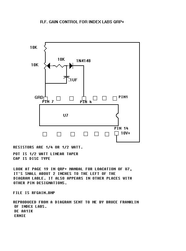
From Larry East, W1HUE, on 10 Nov, 1996
-
I could never understand how changing a resistor in the QRP++ to reduce the audio level into the SCAF could cure the "AGC Thump" problem. Well, it was finally explained to me in a letter from Bruce Franklin of Index Labs. Bruce wrote:
-
The new version of the QRP PLUS has back-to-back Shottky diodes [D2 and D3 on the RF board] connected as a limiter on the output IF stage. The purpose of the limiter is to prevent attack overload on the AGC. The limiting should occur about 6 dB above he AGC threshold.
Unfortunately, a number of units were shipped with an incorrect value for R33 on the audio PCB. This spoiled the gain relationship with the result that the AGC improvement was not achieved. We sent out a letter and a resistor to he customers to correct the problem. With the correct relationship between the AGC threshold and the limiter, the AGC attack performance is very good on the new version."
-
From Larry East, W1HUE, on 27 Nov 1996
-
David W7AQK asked:
-
The other problem is something I seem to remember previous comments about. That is that there is a bad problem with blocking from adjacent signals even if they are only "moderately" stronger than the signal I am trying to copy. The adjacent signal needs to be definitely stronger to cause this, but it sure doesn't have to be a barn burner. The variable filter doesn't seem to help much, if any, in these situations.
This problem results from the "fix" made by Index to solve the "AGC Thump" problem in the QRP++: A limiter (consisting of two diodes) is located at the output of the IF amp to keep the signal level entering the SCAF filter at a reasonable level so that the AGC has time to respond to strong signals. (The signal delay time through the SCAF was the cause of the "Thump" on strong signals; the limiter keeps signal levels from exceeding the AGC threshold by more than a few DB until the AGC has time to respond.) Anyway, the down-side is that strong signals outside the SCAF passband will activate the limiter, thus also limiting the amplitude of signals within the SCAF passband. Narrowing the SCAF only makes matters worse in a crowded band! (Kinda obviates the advantage of a narrow filter...). My solution to the "AGC Thump" problem in the QRP+ was to add a limiter AFTER the SCAF. Strong signals outside the SCAF bandpass might still overload the SCAF causing some strange "squeaks" and "howls", but at least they do not result in signals within the SCAF passband being attenuated. Unfortunately, the IF limiter in the QRP++ cannot be simply deactivated because it is also used during transmit to limit the amplitude of the RF signal feeding the driver amplifier. In fact, it is this limiter that provides the "speech processing" in SSB mode! So... what to do? I don't know, other than add an RF gain control which can be used to reduce the strength of the offending signal(s). A simple RF gain control circuit is available from Index. The big problem is figuring out where to put an RF gain control pot! About the only alternatives are on the back, top of side of the rig.
As for the receiver having to be turned on twice before signals come out, this sounds like a reset problem in the SCAF filter. I managed to "self-inflict" such a problem in my QRP+ when I increased the size of a bypass cap which turned out to cause the SCAF reset line to rise too slowly to affect a reset. Sounds like your rig has a similar problem; I suggest that you contact Index.
-
From Larry East, W1HUE, on 16 Dec, 1996
-
I had a couple of responses from folks that said that they had adjusted the IRF510 final bias as per the instructions in the manual: set it so that the current with no (or very little) transmitted output is 60mA higher than the minimum setting. However, they have not looked at the SSB output on a 'scope.
Here's the problem: I adjusted the bias on my rig as per the manual instructions (it has the direction of the pot for minimum current backwards, by the way...). I tried to make a couple of contacts on 15M SSB but was told that my audio was severely distorted. I made a check with a local on 75M, and he told me that he didn't think the audio "sounded right" and that my signal seemed pretty broad. I then decided to look at the transmitted signal on my 'scope. The SSB modulation looked horrible! I then fed a two-tone audio signal into the mic input, looked again, and it still looked horrible! Severe negative-going clipping resulting in zero RF output for at least 30% of the time. No wonder there was severe audio distortion and splatter!
I then adjusted the bias until I got a decent looking two-tone output on the 'scope -- this required that the idle current be increased to at least 500mA above the minimum setting. Maybe the manual has a misprint, and it should have said 600mA??
I also noted that the positive going peaks were clipped (or limited) at peak power outputs greater than about 3W on the low bands (160-40M) and at less power on the higher bands (about 1.5W on 10M); this could not be eliminated by adjusting the bias. Clipping is pretty severe at 5W output with the two-tone signal. I could also see the clipping on the 'scope when speaking into the mike. By the way -- I have added a pot which allows me to control the ALC level and thus control the SSB power output.
Turns out that before I decided to adjust the bias, the no-signal transmitter current was about 850mA. Minimum current is 435mA, so it was running about 415mA above minimum. (That's the way it was set at the factory.) I primarily operate CW, but I had made a few SSB contacts (before deciding to adjust the bias) with no complaints about the audio quality -- although I was only getting about 3W peak output.
This past week I borrowed a spectrum analyzer and looked at the SSB output. Adjusting the final bias for minimum "hash" on the spectrum analyzer yielded an idling current of 550mA above the minimum -- again about 10X higher than indicated in the manual. However, the clipping that takes place above 3W peak output did not seem to be causing much in the way of spurious output as far as I could tell from the spectrum analyzer.
Saturday afternoon I made two SSB contacts on 17M with the rig. Final bias was set to give an idling current of about 980mA with a supply voltage of 13.1V (normally 13.4V but I get 0.3V drop across the meter). The ALC was set to give a peak output of about 4W -- enough to make the audio peak limiting evident on the scope. Both contacts told me that the audio sounded good; one even said it was "excellent". I also made a check with a local station on 75M, and he also said it sounded good.
I would sure like for someone out there to verify my findings. It does not take a fancy spectrum analyzer, just a 'scope that can display the carrier modulation. A simple "monitor scope" should work fine. And if you don't have a two-tone audio generator, just look at the output while talking into the mic. Check the idling current before you start. Then set the bias to the "60mA above minimum" as per the manual and tell me what you see...
From Larry East, W1HUE, on 17 Jan, 1997
-
The following was received from Peter Zenker, DL2FI, in response to my request for information concerning the IRF510 bias setting in the QRP+:
-
When I did the first review on QRP+ Serial number 253 abt two years ago, I found that the SSB quality was very poor. When I measured what happens at the balance modulator, I found out, that the ALC shortened in SSB the DSB signal to a level of abt some 50 mV, in CW the level was abtout 3 to 4 times more. The ALC did a kind of clipping. I introduced a pot to adjust the ALC level. Although I now could ajust the ALC, the SSB signal stayed bad. Other OMs said my signal sound is like an AURORA signal :-((
Next try was to optimize the output transformer. Things have gone little better with a two hole transformer but still bad. Next I tried some experiments with the "standing current" (I know, that a MOS is voltage driven, but its easier to discuss it in terms of better known standing current as a result of the gate voltage) What I found out was, that it was absolute impossible to have linear amplifier in mode AB with the IRF at 12 Volt. If using more then 18 Volt it was no problem, to run AB (low standing current" and amplifying linear. At 12 Volt the only way was to run the IRF total in A Mode, that means at least 800 mA with now signals. The best results at 12Volts I had at total curent of about 1A with no signal. At this rates the SSB signal is absolute linear, poor (low) distortions and also the reports of critical friends are excellent.
By the way: the IRF runs very, very hot in this mode!!!!!
I verified this expierience in the meantime with 3 or 4 different QRP+ serial numbers 500 (My own one) and up to 1200something. Some other QRP+ users in Berlin did the same test (most of them without modified ALC) aand hat the same results. Last year we measured the Current of very fresh delivered QRP+ (pull out the fuse and use a mAMeter iinstead of the fuse for a fast overview) All !! of this QRP+ showed currents between 800mA and 1200 mA original as from the factory.
This problem is not a Problem for me, because I am a CW only op. But some of my friends like to do SSB to. Most of them modified the QRP+ to run the IRF with more than 12 Volt. Some of them with 2*12V batterie and some with a step up Voltage doubler. These 24V driven QRP+ are very well in SSB and also very stable.
We built the voltage-doubline circuit outside the QRP plus. My QRP+ is housed in a aluminium box with a build in 7Ah Akku, Matchbox and so on ( My "Shack in the box" :-)) ) I opened the +12V for the IRF, put a new plugin at the back side. For normal CW use there is a switch at the backside to, that puts the 12V back to the IRV + line, for SSB I can use the second plugin with a 20-28V Source. I use a step up converter, which I got as a kit from a ham friend, but some others use 2 12V akku in line or different step up convertres. Most are based on one of this MAX chips. It should give you between 20 and 28 V at 1 Ampere minimum. Some Others use a commercial 12 to 24 V supply, we can buy here at a local electronic shop.
So... confirmation that the bias setting instructions in the QRP+/QRP++ manual are INCORRECT! If you adjust the idling current for an increase above minimum of only 60mA, you will have a very poor sounding SSB signal! If you adjust it for an increase of 600mA, it should be pretty close to the optimum value. If you change the bias setting from its factory setting, I strongly recommend that you check the SSB output signal on a 'scope.
-
From Larry East, W1HUE, on 3 Feb, 1997
-
I think I have solved the linearity problem in my QRP+ and the consequent low SSB output power: I replaced the IRF510 final with an MTP3055E along with a new 12:1 output transformer and some negative feedback. I also made some changes to the ALC circuit. The net result is that I can now get a good solid 5W of SSB out on all bands (actually, I can get at least 8W on 160 through 40M) with no signs of distortion. The MTP3055E also operates with a more reasonable idling current of 150 to 200 mA (500 mA or more is required with the IRF510). Still making measurements -- hopefully I'll get finished in time to include this mod in my "QRP+ Mods Part II" article scheduled for the April issue of The QRP Quarterly.
In case you haven't noticed, the QRP+ (and, I assume, the QRP++) SSB output starts to limit above about 3W on the low bands, and at about 1.5W on 10M. It CAN be pushed to 5W out on 40M and below (about 4W on 20/15), but operation in this range is anything but linear. However, the output still sounds reasonably good even though definite voice peak limiting can be seen on a 'scope. For it to operate at all on SSB, an idling current of at least 500mA is required, rather than the 60mA claimed in the manual.
From Larry East, W1HUE, on 7 Jun 1997
-
My dull little brain has finally figured out that there are TWO sources of "chirp" in the QRP-PLUS: 1) The PLL settling time when RIT/SPLIT offsets greater than a few kHz are used, and 2) the rise-time of the BFO offset switching signal. (The 650-700 Hz shift in CW transmit/receive frequencies takes place in the BFO, NOT the VFO/PLL circuit). Keying chirp due to either cause is more likely to show up after installing the "Rev 4C" EPROM; this is due to the faster QSK (especially when using an external keyer) provided by the firmware in this EPROM. For some reason (which my dull little brain hasn't figured out yet), the chirp caused by the BFO frequency switching is more noticeable above 30M (20M and higher).
You can check for chirp by listening to the keyed output of your QRP+ (run it into a dummy load!) on another receiver, or by on-the-air tests with a local ham. It is most instructive if you can actually listen to your signal -- either in a local receiver or over the phone from another ham.
The good news is that both chirps can be easily cured; the bad news is that you have to remove the top three boards from the rig to do it. Both fixes are accomplished by replacing some caps on the LO board (the third one down in the stack). The chirp fixes described below apply to BOTH the QRP+ (original version) and QRP++ ("new improved" or "updated" version). I will also repeat a fix for "soft keying" in the QRP+ that was posted previously (and also described in my April 1997 QRP Quarterly article).
Fixing Chirp due to BFO Switching
-
Change C3 on the LO board from 1.0uF to 0.1uF. Look for a green trimmer cap (shown as C56 in the schematic) near the front right corner of the LO board. C3 will be just slightly to the rear of the trimmer and very close to the right edge of the board; it's a small dipped tantalum, probably orange or yellow in color. Replace C3 with a small 0.1uF mono cap rated at 25V (or higher).
Fixing RIT/SPLIT Chirp
-
Change C43 and C44 on the LO board from 4.7uF to 2.2uF. These caps are in the PLL low pass filter and are located near the right rear edge of the board. The original caps are dipped tantalum; replace them with 2.2uF dipped tantalum, rated at 16V or greater. There should be no noticeable chirp now for RIT/OFFSET splits below 10kHz (probably more like 20kHz to 50kHz).
Fixing "Soft Keying" in the QRP+
-
THIS DOES NOT APPLY TO THE QRP++!
After installing the Rev 4C EPROM in my QRP+, I noticed that the keying was very "soft" unless RIT was used. I discovered that the problem was due to a long time constant in the +12V decoupling to the first driver stage resulting in about a 10ms rise in the keyed waveform (one would like no more than about 5ms). I fixed the problem by changing C54 on the RF board (the top board) from 4.7uF to 0.47uF. C54 is located in the rear left-hand quadrant of the board. The original C54 is a dipped tantalum, and I used the same type (but a factor of 10 smaller in value) for replacement. The voltage rating of the replacement cap should be at least 16V (preferably 25V to 35V).
-
From Jeff M. Gold, AC4HF, on 07 Jun 1997
-
My QRP++ with the newer mixer stopped receiving real well, and only would transmitt in the milliwatt range. All other functions worked.
When taking the rig apart we couldn't get the old mixer from the board. What we did was to cut the top part of the case, carefully off. Then I took great care and cleaned all the silicon looking goop and all other stuff out.. well Conard Murray did the first round of everything (WS4S). We stuck a SBL-1, by soldering the SBL-1 directly to the leg parts that remain sticking up from the mixer after you gut it. The reciever worked ok, but it would only put out about 3 watts on the higher bands and go down to about 1/4 watt on 160 meter.
I sent about $25 off to index and ordered a replacement mixer. It took a little over a week and I did recieve it. I think this was a decent turn around time.
Decided to try to replace the mixer myself. I used solder wick and cleaned the solder off and pulled the SBL-1 off and then carefully soldered the new mixer to the top of the legs sticking up from the gutted old mixer.
I fired up the QRP++ I now get over 5 watts out and everything is working fine. I backed the power down to 5 watts. It gets higher power on the lower bands like it used to.
So for the people who say these mixers never go.. scientific evidence point to the fact that they indeed do. I had a bad SBL-1 on my HW9 right out of the box.. and this new mixer blew from who knows what.
So if you are not a tech wiz and you have burnt out your mixer. Get a direct replacement.. just cut the top of the case of the old one off and solder directly to it. Also, if it blows for some reason.. not a major deal to repair at this point..
From Barry Keating, WD4MSM, on 18 Nov 1997
-
The Index QRP+ rig has a nylon shaft on the rear for adjusting the power level. The shaft is a slotted nylon shaft with grooves down the sides.
There must be a knob which will mate with this shaft (but I have not been able to find one). It is darned difficult to adjust down to milliwatt levels and back up to full power without a knob.
Anyone know of a particular knob for this shaft?
From Stephen Lee, AB7HI, on 18 Nov 1997
-
A standard wall switch dimmer knob will work fine business. Saw a bunch at Home Depot the other day so it is not necessary to buy the entire dimmer just to get the knob. They have the knob all by its lonesome. Enjoy!
From Ernest Gregoire, AA1IK, on 19 Nov 97
-
Hello Barry, don't even try. You won't like it. There is a better way.
The pot inside that is connected to the shaft in question is a cheap little pot that will not withstand a bump from the outside. this is why there was no knob put on it by the manufacturer.
The solution is to replace the pot. Digi key has the pot, and while your at it you might just as well replace the other pot and do an RF gain modification.
This mod is easy to do and gives the SCAF much more control. You will be able to isolate signal that would be overwhelmed by strong signals before the mod.
From Sam Billingsley AE4GX on 12 Dec 2000
-
Subject: Using the INDEX QRP+ or QRP++ on PSK31 **Solving a Rx/TX shift problem **
Stan/K7SY and I have been exchanging emails regarding problems related to my specific INDEX QRP+ SN928 unit.
My basic problem was when finding a station calling CQ and setting my TX cursor (using Digipan V1.5) my TX center frequency would be about 40-50 Hz off the other station hence he could not copy me without moving his RX cursor. With Digipan1.5 you have two RX windows (only one is active for TX) so you can compensate for the INDEX shift if you run a few tests with someone to determine your actual shift. You may have no problem at all so this may not apply to you.
Since Stan and I have solved other INDEX problems in the past I am use to disassembling the INDEX (neat stacked boards with ribbon cable interconnections and other coax connections) so I was not afraid to take it apart to experiment.
Using my ICOM756 has a RX monitor I probed the LO output and BFO outputs in RX and TX PSK operation (into dummy load of course). On my unit I found that the LO was stable between RX and TX changes (ie no freq. shift) but the BFO was in fact the culprit and displayed 40-50 Hz shift when going from RX to TX under PSK (SSB) conditions.
Using the schematics published in my INDEX users manual (with component ID mask drawings too) I was able to find the BFO circuit and look closer to it. My unit has a single transistor colpitts oscillator with a 50 mHz xtal being pulled with 30pF trimmer in SSB and parallel forward conducting diode in CW mode. While my schematic showed the collector getting a +12v (direct battery) the unit had , in fact, been factory MODed to take +8.5V from regulator U7. U7 supplies voltage to the VCOs and all the CMOS PLL ICs thus involved will all critical freq. controlling circuits. I can tell you that a pulled 50 mHz xtal osc. if just looked at will change freq (just kidding but any slight voltage change will be noticable).
I stiffened the BFO osc. voltage by placing a dedicated 78L08 with diode in GND lead to create 8.7V to BFO circuit. Same type circuit used in U7 but now the BFO was isolated. Shift delta improved slightly now was down to about 20 Hz. Better but still too far out for RX and TX sync in same Digipan window. BTW earlier SN rigs have not have the U7 MOD.
Stan suggested that later QRP++ had additional LP/PAD in between BFO output and the transformer and mixer points. So I added a 3 dB resistor PAD just to see the effect of BFO load isolation. Right idea ....... now the Shift was about 6 Hz but still too far for syncing in one window.
So I rebuilt the PAD into a 6 dB resistor PAD and the shift dropped to NIL or nearly so. Obviously since my BFO output drive was reduced by 6 dB to the RX and TX mixers my signal suffered but the load shift isolation point was demonstrated.
The confirm the changes I checked into the North Georgia QRP Club PSK31 net on 3581 kHz tonight and had not problem (except for my weak signal) chatting with NCS for a good period of time.
At this point I plan to add an FET amp back between the PAD output and mixer input points. This should restore my normal TX levels and the RX signals should come back up.
BTW while checking the rig's U7 (the main regulator for the 8.5V source) I noticed that the original resistor R30 supplying zener drive to the GND point of the regulator was still there so I removed it. I don't have the resistor in the added BFO osc. regulator either.
Now I don't know if any of you have experienced the apparent shift problem with one of your INDEX rigs or not. But if you had trouble making contacts or getting anyone to reply to you CQs then I recommend that you check the shift in you rig.
The simplest way is to use Digipan 1.5 and call CQ in one window and when someone replies and you can't decode them but see a good strong signal then set the 2nd Rx window on them and using the SWAP feature and the DISPLAY Freq. check the Hz differences between the two and you'll have a starting point. Just by clicking the two cursors you can setup the other guy hat answers you but you will need to specifically set the two window freq difference to first hear someone else calling and be able to respond and get them to answer without them having to touch their PSK software or rig RIT.
BTW the INDEX has fixed SSB sideband selection that follows the original SSB freq. plan (ie LSB for 40 mtrs and below). I see no problem when I'm running LSB and the other guy is running USB other that specify freq. display differences.
If you have an INDEX gathering dust then check it out for a neat all band PSK xcvr that takes up almost no space next to you PC and if you have a LAPTOP with sound capabilities you may have a good travelling PSK companion.
From: Sam Billingsley on 13 Dec 2000
-
Subject: BFO output Isolation Daughter Board to enable PSK via My INDEX QRP+ Rig SN928
This is a followup to my previous msg. I did build the daughter board that plugs in between the BFO cable and the Mixer input input connector on the top PCB.
Warning: this may not be necessary on your Rig so check first.
Using a 6dB resistor PAD into a J310 FET with an untuned output transformer FT37-61 6T primary and 2T secondary. The levels were such that I didn't have to put an output PAD behind the FET amp stage. Your results my vary. I used my Wes Hayward S.A. to check before and after levels. J310 had source grounded and the primary was connected to 12V via a 120ohm resistor and 0.1 decoupling cap. The FET was directly connected to the output of the 6 dB PAD. I know the purest will say I needed a 50 ohm load there but what the heck!
Now the AF output from the RX is back to normal levels as is the TX output levels. The signal looks very clean on the S.A.
The good news is the BFO shift is GONE and I can operate PSK in one Digipan window.
Here's a couple of PIXs of the daughter board. I used ugly construction and nothing except the levels in critical. I plan to completely shield the box but left it open for the PIX.
From Earl, VE3AB, on August 23, 2006
-
I changed the SBL1 in my QRP+. Just put in another SBL1. I wrote up the procedure and sent it in to Mike at the QRPARCI for publishing in their magazine. Not sure if it is published yet. I think I still have some files on my web page if you want to contact me directly.
An NE602 type mixer could be substituted but it would require some circuit mods. For a kickoff..the NE602 is active device whereas the SBL1 is passive.
The QRP++ ads mentioned a better mixer made by synergy. Probably had better specs. As far as I know..and from what ive read..the SBL1/diode dbms require a good termination for the mixing byproducts (a good diplexer). Not sure if the QRP+ has good diplexer.
I'd be inclined to use a good old Dual Gate Mixer like the Argonaut 505 and 509 series. You could also use a DG Mixer as an amplier like the Argonaut as well and use the existing front end filters provided by the QRP+ circuitry.
The Argonaut has good ears and is not as prone to front end overload. You would have to build a little circuit board and have this "new front end circuit on it". Doug Demaw did that with the old HW7. He bypassed the old rx front end and then patched it in a little later.